Introduction:
The success of any cast restoration depends upon its fit on to the underlying tooth structure.[1] A deficient margin leads to plaque retention resulting in gingival inflammation, marginal leakage which can lead to secondary caries, sensitivity, gingival recession, cement dissolution and debonding of the restoration.[1],[2],[3] Even though published data on clinically acceptable discrepancies vary from 30µm to 200µm, standard reference4 on cast restorations mention a marginal gap of up to 74µm is clinically acceptable.
Various studies demonstrate that the surface roughness of cast gold alloy specimens ranged from approximately 2 to 30µm on an average.[5] A smooth surface not only prevents plaque and calculus accumulation, but it also improves the corrosion resistance of the alloy. The surface roughness on the intaglio surface of the cast restoration affects the fit of the restoration.
Conventional investing and casting techniques, usually require at least 1 hour bench set for the investment, followed by a one, two or three stage inlay wax and pattern resin elimination cycle as recommended by the manufacturer before the casting procedure.[4],[6],[7],[8] The whole process is time consuming and requires approximately 2 to 4 hours for completion.[6],[7]
The accelerated casting techniques have been reported in an effort to achieve similar quality results in significantly less time.[6],[7] The pattern is invested, cast and delivered in a cost effective, time saving manner. This combination offers many advantages to the patient, dentist, and dental laboratory technician, and has received increased attention as a method of improving productivity.[7] Some studies[6],[7],[9] have reported that this procedure is technique sensitive. However, the effect of accelerated procedures on the marginal discrepancy and surface roughness of base metal alloy restorations has not been adequately studied.
Materials & Methods
This study was conducted to measure the vertical marginal discrepancy and surface roughness of base metal alloy cast copings made by Inlay Wax and Pattern Resin with two different methods of casting techniques (conventional casting technique with three stage wax elimination and accelerated casting technique).
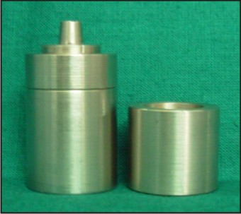
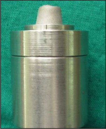
The stainless steel master die and stainless steel former employed in this study was custom made, based on the model employed by Konstantoulakis et al, Schilling et al for their studies. This assembly essentially is of two parts, the stainless steel master die and the stainless steel former which fits over the die. The stainless steel master die simulated a crown preparation with a 10-degree total axial wall taper. Four markings present on the base of the die, separated by 90-degree, each serve as standard reference points for measurement of the vertical marginal discrepancy of all the cast copings.
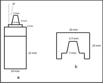
The internal surface of the stainless steel former assembly was larger than the die in all dimensions by 0.5mm uniformly. This was done to maintain a space of 0.5mm throughout between the master die and former to obtain the wax patterns with a uniform thickness of 0.5mm and a 90-degree shoulder margin (Fig. 1), (Fig. 2a, 2b).
 | Figure. 1 : Custom made stainless steel master die assembly
 |
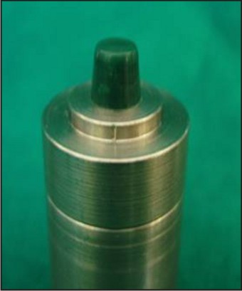
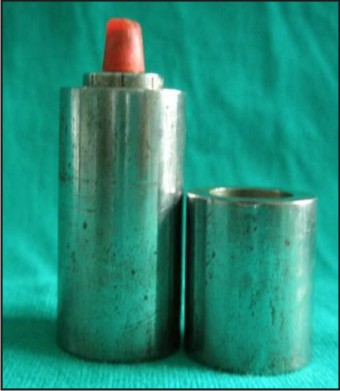
In the present study 20 inlay wax & 20 resin patterns were fabricated (Fig. 3), (Fig. 4) and the sprue was attached to the pattern at an angle of 450. The pattern was removed from the die with a gentle pressure and the other end of the sprue was attached to the crucible former. Surfactant spray was applied to reduce surface tension of all Inlay Wax and Pattern Resin thereby improving wettability with the investment. Inlay Wax and Pattern Resin copings were invested individually with carbon free, phosphate bonded investment material. The liquid is prepared by mixing the PCT Flexvest liquid with distilled water at a ratio of 80:20 respectively to achieve optimum expansion. Weight of 60 gm of phosphate bonded investment was mixed with 13ml of premixed liquid under vacuum using vacuum mixer. The investment pattern was allowed to bench set for 30 minutes. All the 40 patterns in four groups are invested in the same manner.
 | Figure. 2 : Dimensions of custom-made stainless steel master die, a: Line diagram of custom-made stainless steel master die, b. Line diagram of custom-made stainless steel former
|
 | Figure .3 : Inlay wax pattern on the master die
|
The inlay wax and pattern resin patterns obtained were cast by conventional and accelerated casting techniques were described below:
1) G-I:Conventional casting technique of Inlay Wax copings with 3 stage burnout procedure (10 samples): The wax burnout was done by using a programmed preheating schedule, i.e. the ring was kept in the furnace at room temperature and was heated till2700C, with a temp rsie at a rate of 80C / min and was held at this temperature for 30 min. Then the ring was heated from 2700C to 5600C at a rate of 80C rise per min, and was held at this temperature for 30 min. Terminal burnout was carried out from 5600C to 8500C rise of temp at a rate of 80C rise per min and was held at this temperature for 30 min.
2) G-II:Accelerated casting technique of Inlay Wax copings with single stage burnout procedure (10 samples): After a 30 minute bench set time, the set invested ring was placed directly in a preheated burnout furnace at 8500C, and held for 30 min to ensure complete burnout of the wax pattern.
3) G-III:Conventional casting technique of Pattern Resin copings with 3 stage burnout procedure (10 samples): Same as G-I technique but 10 min extra time is needed for burnout.
4) G-IV:Accelerated casting technique of Pattern Resin copings with single stage burnout procedure (10 samples): After a 30 minute bench set time, the set invested ring was placed directly in a preheated burnout furnace at 8500C, and held for 40 min to ensure complete burnout of the Pattern Resin.
The casting procedure was performed quickly to prevent heat loss from the ring, which may result in the thermal contraction of the mold. The preheated casting crucible and the investment mold were taken out of the furnace and were placed in the casting machine. The Nickel-Chromium alloy (CB 80, non precious alloy, DENTSPLY) was heated sufficiently till the alloy ingot turned to molten state and the lever was released and centrifugal force ensures the completion of the casting procedure. Investment was allowed to cool down to room temperature and the casting was retrieved.
Adherent investment was removed from the casting initially with hand instrument and then by sandblasting with 110 micron alumina at 80 psi pressure. The sprue was cut and removed at the junction of the coping with an ultra thin abrasive disc and the copings were subjected to ultrasonic cleaning & checked visually for any casting defects.
Each casting was seated on the stainless steel die with finger pressure until resistance was met (Fig. 5). Microscopic measurements were recorded at 80 X magnification perpendicular to the axial wall with a photomicroscope (Reichert Polyvar 2 met photomicroscope, Reichert, AUSTRIA). Marginal discrepancies were measured to the nearest micron on each casting at the four predetermined sites on the base of the stainless steel die separated by 900 each.
For measuring surface roughness the cast metal coping should be held exactly perpendicular to the diamond indenter. A stainless steel custom made coping holder was used for measuring surface roughness with a depression horizontally in the center to accommodate the coping precisely in to it (Fig. 6). The surface roughness was measured by passing the diamond indenter over the coping surface for a distance of 1.6mm.The readings were obtained graphically as crests and troughs with surface roughness analyzer (Taly Surf Computer Guided Surface Roughness Analyzer, Kosaka Lab). Surface roughness was measured to the nearest micron at 3 surfaces on the coping. The measurements thus obtained were tabulated and statistically analyzed.
 | Figure. 4 : Resin pattern on the master die
|
 | Figure .5 : Cast coping seated on the master die
|
Results:
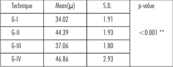
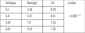
The obtained results were statistically analyzed by t-test. In the present study, p<0.001 was considered as the level of significance. The results show the comparison of the mean value of the vertical marginal discrepancy and surface roughness values obtained for each of the four techniques. (Table. 1 & Table. 2) Since the p-value is less than 0.001, there is highly significant difference between the four techniques with regard to vertical marginal discrepancy and surface roughness. Higher values of vertical marginal discrepancy were found with accelerated casting techniques G-II (44.39µ) and G-IV (46.86µ) when compared to the conventional casting techniques G-I (34.02µ) and G-III (37.06µ) and this difference was statistically significant. Higher values of surface roughness were found from castings done with Pattern Resin in both G-III (7.8µ) and G-IV (9.24µ) techniques and this difference was statistically significant.
 |
|
 |
|
Discussion:
The conventional investing and casting techniques require at least 1 hour bench set for the investment. The usual burnout temperatures for phosphate-bonded investments range from 7500 to 10300C. The highest temperatures are required for base metal alloys, especially those that are used for ceramometal restorations. Initially one stage wax burnout procedure was followed traditionally to achieve complete burnout as well as thermal expansion. The entire process involving phosphate-bonded investments takes a long time; the demand for time saving is more. Accelerated casting techniques have the ability to shorten the investing and casting process, there by improving productivity. This accelerated technique uses a typical method of setting and burnout of the phosphate-bonded investment.
The first published attempt to accelerate the lost wax technique with the use of phosphate-bonded investment for complete crown was made in 1988 by Marzouk and Kerby. Campagni et al[10] tested the fit of dowel and cores made of noble alloy by an accelerated casting technique, and similar studies were subsequently conducted by Bailey and Sherrard and Schneider.[11],[12] All these investigations concluded that the use of a predetermined bench set time reduced investment weakness and that standardized accelerated procedures for all types of investments were inadvisable.[7]
Konstantoulakis[6] andSchilling et al[7] evaluated the marginal fit and surface roughness of complete cast crowns made with a conventional and accelerated casting technique and reported that crowns fabricated with the accelerated casting technique were not significantly different from those fabricated with conventional technique. The accuracy of base metal alloy castings obtained by different investing and burnout procedures with phosphate-bonded investments were not adequately studied.
Surface roughness of dental castings is an important aspect of their quality and can potentially affect their marginal fit and the time required for finishing and polishing. Surface roughness of castings is believed to be affected by several factors such as type of alloy, mold material, mold temperature, wax pattern, and casting machine.[6]
The basic data for vertical marginal discrepancy shows a mean value of 34.02 µm for G-I, 44.39 µm for G-II, 37.06 µm for G-III and 46.86 µm for G-IV techniques. The surface roughness shows a mean value of 4.38 µm for G-I, 5.41 µm for G-II, 7.80 µm for G-III and 9.24 µm for G-IV techniques.
The statistical analysis by t-test indicated that the difference in the vertical marginal discrepancy and surface roughness measurements for the four techniques showed the p-value of < 0.001. This denotes significance at 1% level.
The results indicate that, with in the limitations of the study, the castings produced by conventional casting technique showed a lesser vertical marginal discrepancy and surface roughness values than the castings produced using accelerated casting technique. The castings made with Inlay Wax have lesser marginal discrepancy and lower surface roughness values when compared with the Pattern Resin.
Longer burn out cycles as recommended by manufacturer were used in this study and was probably the reason for lesser vertical marginal discrepancy and surface roughness values of castings made by conventional casting technique as compared to the castings produced using accelerated casting technique. Accelerated techniques may take advantage of characteristic exothermal setting reaction of phosphate-bonded investments. Heat-enhanced setting expansion continues uninterrupted as the mold is transferred into a preheated furnace for thermal expansion.[7] This may probably be the reason for the marginal discrepancy and surface roughness of cast copings by accelerated technique to be with in the clinically acceptable limit.
Accelerated casting technique has greater marginal discrepancy when compared with the conventional casting technique. This may be due to bulk addition of the material. Most of the literature on accelerated casting technique shows better marginal fit with intra-coronal restorations. However further research to be done on the extra-coronal restorations.
In this study the surface roughness of resin pattern is greater than the Inlay Wax. This may be due to the greater size of the polymer beads (approximately 150µm) [13] and also due to evaporation of the monomer which could not be controlled. The surfactant which is used to decrease the surface tension and contact angle probably has the little effect in improving the contact of the investment with the pattern.
The results of this study encourage further research with accelerated technique and reinforce the need to identify the factors that facilitate better marginal fit and surface roughness of cast restorations. Only one single wax pattern is investigated per casting in this study. The performance of the described accelerated casting technique when more than one wax pattern or fixed partial dentures invested in the same ring requires further investigation.
Conclusion
The following conclusions were drawn from the data obtained in this study:
1. The order of vertical marginal discrepancy of the cast copings:
a. Least marginal discrepancy - G-I (34.02 µm).
b. Moderate marginal discrepancy- G-III (37.06 µm).
c. Maximum marginal discrepancy - G-II – ((44.39 µm) and G-IV – (46.86 µm).
2. The order of surface roughness of the cast copings:
a. Least surface roughness - G-I – (4.38µm).
b. Moderate surface roughness - G-II – (5.41 µm).
c. Maximum surface roughness - G-III – (7.80 µm) and G-IV – (9.24 µm).
3. The mean vertical marginal discrepancy and surface roughness of all the cast copings obtained by the four techniques (G-I, G-II, G-III and G-IV) were within the clinically acceptable limits.
References
1. Bronson MR, Lindquist TJ, Dawson DV. Clinical acceptability of crown margins versus marginal gaps as determined by pre-doctoral students and prosthodontists. J Prosthodont. 2005; 14(4): 226-232.
2. Boeckler AF, Stadler A, Setz JM. The significance of marginal gap and overextension measurement in the evaluation of the fit of complete crowns. The Journal of Contemporary Dental Practice. 2005; 6(4): 1-12.
3. Holmes JR, Bayne SC, Holland GA, Sulik WD. Considerations in measurement of marginal fit. J Prosthet Dent. 1989; 62(4): 405-408.
4. Anusavice KJ. Phillips Science of Dental Materials, 11 Ed. Philadelphia: WB Saunders Co; 1996: 295-350.
5. Bedi A, Michalakis KX, Hirayama H, Stark PC. The effect of different investment techniques on the surface roughness and irregularities of gold palladium alloy castings. J Prosthet Dent. 2008; 99(4): 282-286.
6. Konstantoulakis E, Nakajima H, Woody RD, Miller AW. Marginal fit and surface roughness of crowns made with an accelerated casting technique. J Prosthet Dent. 1998; 80(3): 337-345.
7. Schilling ER, Miller BH, Woody RD, Miller AW, Nunn ME. Marginal gap of crowns made with a phosphate-bonded investment and accelerated casting method. J Prosthet Dent. 1999; 81(2): 129-134.
8. Rudd KD, Marrow RM, Eissmann HF. Dental Laboratory Procedures. Vol 2. St.Louis; The C.V. Mosby Company: 1986: 213-220.
9. Blackman RB. Evaluation of the dimensional changes and surface roughness of gold crowns cast with rapidly prepared phosphate-bonded investment: A pilot study. J Prosthet Dent. 2000; 83(2): 187-193.
10. Campagni WV, Reisbick MH, Jugan M. A comparison of an accelerated technique for casting post-and-core restorations with conventional techniques. J Prosthod.1993; 2(3): 159-166.
11. Bailey JH, Sherrard DJ. Post-and-core assemblies made with an accelerated pattern elimination technique. J Prosthod. 1994; 3(1): 47-52.
12. Schneider RL. A one-appointment procedure for cast post and core restorations. J Prosthet Dent. 1994; 71(4): 420-422.
13. Richerd Van Noort. Introduction to Dental Materials. Third edition: MOSBY ELSEVIER Publishing Co, Inc; 2007.
|