INTRODUCTION
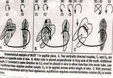
Vanarsdall & Swartz1 said that due to early loss of permanent molars the adjacent teeth tilts mesially , molar uprighting involves the correction of these mesially tilted molars. M.U.S.T was originally done by Elie Capelluto & Isabelle Lauweryns2 to upright mesially tilted molars without extrusion. In the study by Drescher & colleagues only the burstone uprighting spring made of TMA wire produced an intrusive force during the molar uprighting. However this spring required delicate control since small differences in the bending angles could change the force delivery considerably. Recently they introduced a new uprighting spring consisting of a titanium wire connected to mesial & distal stainless steel wire which are fixed to attachments on the premolar & second molar. While the spring was shown to produce both an up righting moment & an intrusive force on the molars , it is still difficult to adjust in mouth . Melsen & colleagues pointed out the significant changes in a geometry V force system delivered by a T loop or V bend that are caused by displacing the loop to one side or the other. They suggested a two cantilever system for uprighting molars. Since both the forces produce uprighting moments, activation is controlled by varying the relative moment to force ratios of the
cantilevers. This method although provides better control of the moments, is difficult & complex in execution.
Edward H. Angle3 called the first molar the “key to occlusion”. Graber.T.M4 said that the early loss of first permanent molars leads to mesial migration of the adjacent teeth that is the second permanent molar and the third permanent molars are tipped mesially or rotated. These are in such position that is conducive neither to a long term health nor to simple restorative procedures. In addition the premolars may have drifted distally and rotated, resulting in open contacts in poor marginal ridge relationships. The opposing teeth may supra erupt into the edentulous space further
complicating the situation.
These mesially tipped or tilted molars cannot be used as an anchor molar as the forces will lead to further tipping of the molars. As the teeth moves mesially the adjacent tissue becomes folded and distorted forming a plaque harboring pseudo pocket which may be virtually impossible to clean thus leading to accumulation of bacterial plaque
which damages the periodontium by stimulating an immune response.
AIMS AND OBJECTIVES
This study was conducted to –
1. Evaluate the efficiency and performance of molar up righting simple technique M.U.S.T without extrusion.
2. Evaluate the model, and cephalometric changes encountered during the molar up righting.
MATERIALS AND METHODS
1. Two molar tubes Size-0.018’’ x 0.025’’ Torque - 0 degree torque
2. Active Component Super elastic 0.016’’ x 0.022’’ nickel titanium wire
3. Glass ionomer cement Powder + liquid
4. Molar Band
Size-180’’ x 0.005’’
 | Fig 1
 |
 | Fig 2
|
APPLIANCE DESIGN AND BIOMECHANICS
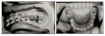
One 0.018’’ x 0.025’’ molar tube is soldered cervically to the molar tube parallel to the occlusal plane .A shorter 0.018’’ x 0.025’’ tube is soldered horizontally to the cervical area of the premolar. Both the tubes have a 00 torque. The active
component 0.016’’ x 0.022’’ super elastic nickel titanium wire extends from the mesial of the premolar tube to the distal of molar tube. Each end of the wire is covered with glass ionomer cement to avoid irritation and distortion. The area
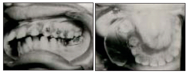
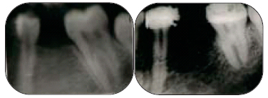
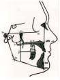
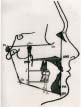
anterior to the molar can be stabilized with lingual bar or lingual button connected with passive elastic chain or with anchorage to the fixed appliance. (Fig – 1). pre treatment & post treatment intra oral periapical radiographs were taken for all of the patients . ( Fig – 2 ) . pre treatment & post treatment intraoral photographs were taken for all the patients . ( Fig – 3 ) & ( Fig – 4 ) . pre treatment & post treatment cephalogram were superimposed .( Fig – 5 )
 | Fig 3
|
 | Fig 4
|
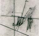 | Fig 5
|
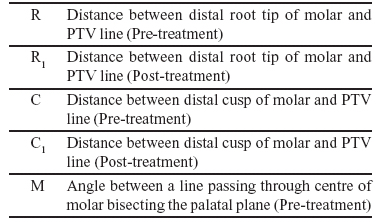
TABLE I: CEPHALOMETRIC LANDMARKS FOR UPPER MOLARS
 | Fig 6
|
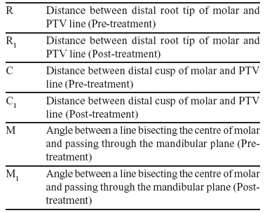
TABLE II: CEPHALOMETRIC LANDMARKS FOR LOWER MOLARS
 | Fig 7
|
NOTE: PTV line was drawn perpendicular to Frankfort plane.
STUDY MODELS
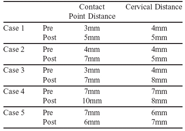
According to “Hom and Turley”5 the mesiodistal distance from the contact point of molar to contact point of the other teeth beyond the spacing was measured with the help of vernier caliper. The distance between their cervical regions was also measured. ( Fig – 8 )
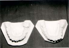 | Fig 8
|
TABLE III: MEASUREMENT OBTAINED BY STUDY MODELS
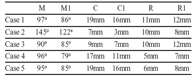
TABLE IV: MEASUREMENT OBTAINED AFTER CEPHALOMETRIC SUPERIMPOSITION
STATISTICAL ANALYSIS [CEPHALOGRAMS]
1 Cephalogram Angular measurement
Mean – 11.2o
S.D – 10.4o
P < 0.05
2 Linear measurement of distal cusp tip of molar
Mean – 3.6mm
S.D – 1.73mm
P < 0.05
3 Linear measurement of distal root tip of molar
Mean – 1mm
S.D – 1.73mm
P < 0.05
STATISTICAL ANALYSIS [STUDY MODELS]
1 Contact Point Distance
Mean – 2.2mm
S.D – 1.9mm
P is less than 0.05
2 Cervical Distance
Mean – 1.2mm
S.D – 1.9mm
P is less than 0.05
RESULT
95% change in crown angulations was noted but the root movement was non significant.
DISCUSSION
A variety of appliances had been proposed to upright tipped molars “Levitas” 6 and “Sim 7 advocated twisting and inserting a brass wire into the contact area of the impacted permanent first molar and the second primary molar so as to force the permanent molar to move distally. “McDonald and Avery” 8 modified it by using self locking separating springs. “Braden” 9 recommended a fixed lingual arch with finger spring to move the molar distally. “Halterman” 10 used elastic
stretched between a long hook soldered to the lingual surface of primary second molar and a button bonded to the first permanent molar. Most of the techniques caused occlusal crown movement that is along with up righting slight
extrusion was also noted. M.U.S.T appliances are easy to use and the superelastic nickel titanium wire produces a distalizing force against the molar tube and an opposing force to the centre of resistance. The more activation is applied more the distalization will occur. The movement delivered by this couple will accentuate the suprighting movement in sagittal plane. Advantages of M.U.S.T was patient comfort, there was no occlusal interference, neither was any wire
deformation from mastication. Intra oral activation was fast and treatment time was relatively short. Furthermore the integrity of the molar was preserved so that no occlusal recontouring was needed after up righting. Findings in this study indicates that orthodontic molar up righting can be achieved with this technique as all the five cases showed significant
molar up righting with a mean of 11.2o angular changes and a mean linear change of 3.6mm in just two months. No root movement was noted. Almost all cases had some pain during the treatment but for a lesser duration. The appliance
was well accepted by all as there was no breakage or dislodgement & no periodontal damage was noticed.
REFERENCES
1. Vanarsdall.R.L & Swartz.M.L : Molar Up righting : Ormco Catalog No. 740-0014,Glendora,Calif-1980
2. Elie Capelluto & Isabelle Lauweryns: A simple technique for molar uprighting.JCO February 1997 Volume xxxi Numberz.
3. Angle.E.H: New System of Regulation and Retention. Dent Register 41: 497-603, 1887.
4. Graber.T.M: Orthodontics: Principles and Practice: E D. 3, Philadelphia 1972, W.B. Saunders Company.
5. Hom.B.M & Turley. P. K: The Effects of Space Closure of Mandibular First Molar Area in Adults. A J O – D O 1984
June(457-469)
6. Levitas. T. C: A Simple Technique for Correcting an Ectopically Erupting First Permanent Molar. J. Dent. Child. 31: 16-18,1964
7. Sim. J.M: Minor Tooth Movement in Children C.V. Mosby Co. St. Louis, 1972, PP.121-122
8. McDonald. R.E & Avery. D: Dentistry for the Child and adolescent ,2nd Ed, C.V.Mosby Co , St Louis, 1974, PP. 382-
387
9. Braden.R.E: Ectopic Eruption of Maxillary Permanent First Molars, Dent.Clin.N.Am.8 (2):441-448, 1964
10. Halterman.C.W: A Simple Technique for the Treatment of Ectopically Erupting Permanent First Molars, J.Am.Dent.
Assoc. 105:1031-1033, 1982 |