Introduction
Extraction space closure is an integral part of orthodontic treatment which demands a thorough understanding of the biomechanics. In this process, it is mandatory to position the teeth in ideal alignment and angulations while maintaining maximal anchorage control.
In the pre-adjusted edgewise technique, retraction is achieved either with friction (sliding) or frictionless mechanics. In the former, the wire and position of the bracket are important factors in tooth movement but the simplicity of friction mechanics is offset by the binding between bracket and arch wire. This slows tooth movement, compromises the delivery of desired force levels, causes anchor loss and may be associated with undesirable side effects such as uncontrolled tipping and deep bite.[45],[46]
The disadvantages of the sliding technique can be overcome theoretically with a frictionless system incorporating a loop as the source of force. One of the major advantages of frictionless mechanics is that a known force system is delivered to teeth because there is no dissipation of force due to friction. The three primary characteristics of a retraction spring are (1) the moment/force ratio which determines the centre of rotation of tooth during its movement, (2) the greatest force at yield that can be delivered from a retraction spring without permanent deformations, and (3) force to deflection rate.[11] The most important characteristic is the moment to force ratio since this determines whether tooth movement takes place by translation or tipping.[11],[7] Literature shows us that the moment to force ratio is altered by the vertical height of the loops,[11] horizontal length of loop,[11] positioning of the loops,[4],[5],[11],[35] extent of activation,[7],[8],[11],[29] properties and thickness of wire [10],[21] used.
Controlling anchorage in three dimensions is one of the most critical elements of orthodontic treatment.[7],[36] Anchorage control involves the ability to create appropriate force systems (stimulus) that will provide the desired treatment effects (response). The problem of anchorage control is rooted in Newton’s third law of motion. Since each end of the spring is activated unequally, this would generate additional vertical forces in the anterior and the posterior segment to keep the system in equilibrium.[36],[39] As these force systems are usually applied to the buccal surfaces of the teeth which is away from the centre of resistance, this would produce a moment which will tend to produce rotation of tooth.[50],[51] Thus anchorage has to be considered in antero-posterior, vertical plane and transverse plane.
Frictionless mechanics have evolved from simple vertical loops to present more complex loop[7],[11],[24],[58],[59] design to achieve better moment to force ratio and constant delivery of force. Materials used for frictionless retraction have also evolved from stiff stainless steel wires to the more flexible beta titanium wires introduced by Burstone,[10] and to the newer materials like CNA wires[45],[46] which are supposed to reduce the force levels and thus making the treatment more effective and efficient.
The literature contains many extensive descriptions of the in vitro static force systems produced by different orthodontic springs[18],[20],[25] and wire activations[27], and the comparison between different springs. Although these models are supported by logical rationale in mechanics, a clinical study comparing different loops will determine whether biomechanics of different loops work as shown and acclaimed by their authors clinically.
The superiority of the “T” loop to the vertical loop is well established in delivering high moment to force ratio and low load deflection rate, thus achieving more controlled movement with higher activation[7],[11],[19],[20] The Mushroom loop[46],[47],[48] advocated by Nanda is an adaptation of T loop, which he professes to be better than the predecessor as it produces increased moment to force ratio and lower force levels, thus providing faster and more controlled space closure.
Thus a clinical study was designed to evaluate and compare the response of the dentition to these two different force system used to bring about en-masse retraction in a maximum anchorage situation by applying differential moments to the anterior and posterior segments. A single activation of the T loop and Mushroom loop was evaluated over a period of two months using lateral cephalograms.
Materials And Methods
Fourteen subjects meeting the inclusion criteria were selected from the patient pool available at the Department of Orthodontics, Sri Ramachandra Dental College, Chennai. The mean age of the subjects at the start of observation was 16 years with a range of 11 to 25 years.
Inclusion criteria required a treatment plan involving bilateral extraction of upper first premolars (with or without extraction of mandibular teeth), with maximum posterior anchorage during space closure. Additionally, all patients were required to have permanent maxillary incisors, canines, and first molars with healthy periodontal support. Oral and written consent for participation was taken from patients.
All teeth were bonded with 0.022 inch by 0.028 inch Preadjusted Edgewise Appliance (Roth prescription). A passive transpalatal arch was fitted to the maxillary first molars to prevent mesiopalatal rotations. Second molars were banded and aligned to enhance anchorage control. Initial levelling and aligning was done till .017 X .025 stainless steel arch wire could be inserted passively. All subjects’ anterior teeth were consolidated up to canine to ensure en masse retraction.
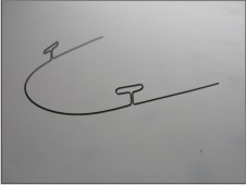
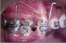
Subjects were divided in two groups of seven each. In Group I, en masse anterior retraction was done with 0.017 inch X 0.025 inch Beta-titanium (Ortho-Organizers , San Marcos, CA) incorporating the continuous T-loop design, as described by Nanda.[45] (FIGURE 1B) Continuous T loop archwire was engaged in the premolar bracket and second molar tubes along with the first molars.
 | Figure 1 B
 |
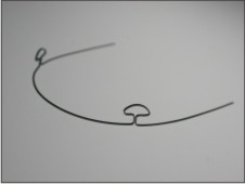
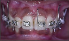
In Group II, retraction was carried out with .017 X .025 CNA (CNA, Ortho-Organizers, San Marcos, CA) continuous preformed mushroom loop arch wires. (FIGURE 1A) The mushroom loops used were of different inter-loop distance i.e. 52mm, 54mm or 56mm depending on subjects inter canine bracket distance. The second premolars were engaged in the archwire.
 | Figure 1 A
|
Both the loops were given at 400 beta and 200 alpha activation (FIGURE 2) to develop the differential moment[45],[48] for group A anchorage (maximum anchorage). The torque in the posterior legs, if any, was eliminated to make the wire passive in the third order in the buccal segments. Each spring was “over bent” to remove residual stresses and trial activated a minimum of four times to ensure dimensional stability. Any resulting distortions were corrected before placement. On insertion, each closing loop was activated six mm.(FIGURE 5A,B) Activation levels of the springs were confirmed with callipers. Once activated, the loops were adjusted for patient comfort but were otherwise left undisturbed during the observation period. An observation period of two months was planned to allow full expression of the force system delivered by the spring under a single activation.
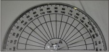 | Figure 2
|
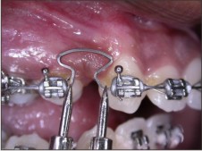 | Figure 5 A
|
 | Figure 5 B
|
Recording Technique
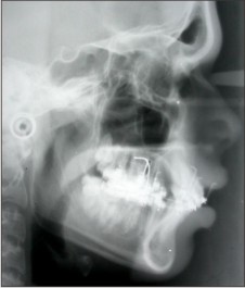
All radiographs were taken with the same cephalostat to minimise the magnification error. To reduce error associated with landmark detection, a tooth positional locating device (TPLD) was fabricated from sections of .021” X .025” stainless steel wires which were attached to the maxillary first molars, canines, and a single central incisor before film exposure. (FIGURE 3A & B) These devices aided in precisely locating the before and after treatment cephalometric positions of the proximate teeth. To differentiate between right and left landmarks, the gingivally directed wire ends of the TPLD used on the right side were bent forwards and those on the left side were bent backwards. Lateral cephalograms were taken just before spring insertion and activation (T1), as well as at the end of the two month study period (T2). (FIGURE 4A).
 | Figure 3 A
|
 | Figure 3 B
|
 | Figure 4 A
|
Superimposition method and measurement technique
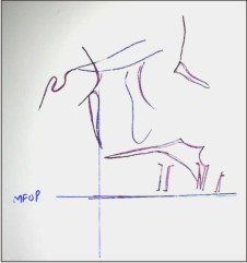
Once the before (T1) and after (T2) radiograph records were collected at the end of the study period, the maxillary and cranial base structures were traced on acetate matte paper using 0.5-mm drafting pencils. All bilateral landmarks were bisected to reduce the images to the mid sagittal plane. Functional occlusal planes as described by Johnston[33] were traced for each film. The structures of the maxillae were then superimposed ignoring dental changes. The superimposition technique was modelled after the structural method proposed by Bjork and Skieller,[2] where structures are superimposed on anterior surface of zygomatic process of the maxilla. (FIGURE 6) After superimposition, a mean functional occlusal plane (MFOP), as described by Johnston,[33] was chosen as a horizontal reference plane. At 900 to the MFOP, a vertical reference plane that intersected common posterior borders of the tracings of the two maxillae was drawn. From this coordinate system, dental changes were assessed. All tooth positions were represented by the traced image of the TPLDs. The measurements were taken from coronal end of the TPLDs to the reference lines to measure the amount of crown movement.
 | Figure 6
|
Data And Error Analysis
Data for bilateral molar and canine movements were combined so that a total of 28 observations of each variable were assessed among the sample of 14 subjects. Descriptive statistics of means, standard deviations, and ranges were computed for horizontal, vertical, and angular dental changes. Paired one-tail t-tests were used to test mean differences between intra subject molar and canine horizontal, vertical, and angular displacements. Mean differences were considered significant at p < .05. The error standard deviation was determined using Dahlberg’s formula.
Variables Measured
The various measurements which were made
1. Anterior segment movement
The distance between canine to vertical reference line was measured at (T1). Same was done after the study period (T2). The difference between T1 and T2 gave the distance of the canine moved.
2. Anchorage measurement
The difference between distances from molar to vertical reference line was measured at T1 and T2. Negative values were assigned to anchorage loss, positive values for anchorage gain.
3. Vertical response
The distance between incisor, canine and molar to horizontal reference line was measured at (T1), same was done after the study period (T2). The difference between T1 and T2 gave the amount of vertical displacement taken place in all three regions. Negative values were assigned for intrusion and positive values for extrusion.
4. Angular response
The change in the angulation of TLPD with reference to horizontal reference plane was measured for molar and canine between T1 and T2. Negative values were assigned for crown tipping, positive values for root movement.
Comparison between T loop retraction and Mushroom loop retraction was done for all the variables considered and evaluated statistically with student (independent) t tests. Mean differences were considered significant at P < .05.
Results
Anterior segment
The canines (representing all six anterior teeth) showed a mean retraction of 2.429 + 0.852 mm with T loop whereas with Mushroom loop it retracted 3.0 + 0.519mm.
Anchorage control
The mean mesial displacement of the maxillary first molars with T loop was -0.143+ 0.569 mm SD whereas the Mushroom loop mean showed molars moving distally by 0.0357+ .746mm.
Vertical response
The mean vertical change of the molars with T loop was 0.07+ 0.0756 mm in an extrusive direction whereas with Mushroom loop the mean vertical change of the molar was 0.464 + 0.720 mm, also in the extrusive direction. Although the mean vertical changes were effectively zero for T loop, a substantial range variation was seen in vertical displacement of molars. The mean vertical change of the canine with T loop was 0.536 + 0.720 mm in an extrusive direction whereas with Mushroom loop the mean vertical change of the canine was 1.0 + .679 mm, also in the extrusive direction.
Angular response
The angular changes for the molars with T loop are centered about a mean of -0.0357 + 2.4220, indicating molars crown tipping forwards into extraction space whereas with Mushroom loop mean molar angular change was 0.464+2.80 indicating root movement. The mean angular changes for canine with T loop were 3.5+1.50where as with mushroom loop it was 2.6+3.00. Both the canine and molars exhibited a fair degree of variability of treatment response to angular changes (Table 1 & 2).
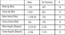 | Table 1 : T Loop Retraction
|
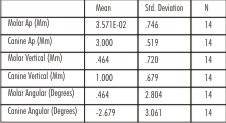 | Table 2 : Mushroom Loop Retraction
|
Discussion
Orthodontic space closure should be individually tailor based on diagnosis and treatment plan. At least six goals should be considered for any universal method of space closure.[7] With sliding mechanics, space closure is slowed as the bracket undergoes “stick-slip” action along the arch wire which may promote rapid changes in the magnitude, location and direction of periodontal strains. It can also be associated with the side effects like uncontrolled tipping, deepening of bite and loss of anchorage.[46]
Well designed closing loops promote a more continuous type of tooth movement by eliminating the intermittent force delivery as seen in sliding mechanics. C.J.Burstone in his “Segmented Arch Technique" had segmented the dental arch into an "active unit/segment" (tooth/teeth to be moved) and a "reactive unit/segment" (anchorage teeth). The active and reactive segments were joined by specialized springs.[6] The advantages of this technique were that it delivered known force systems which were statically determinate and the type of movement of teeth could be controlled by the clinician.
The segmental T-loop closure principles can also be applied to space closure on a continuous arch [45]. In this study a continuous spring rather than the segmental spring was used. The rationale for using a continuous spring was that the continuous-wire spring is more typical of conventional clinical practice than the segmental and secondly, the Mushroom loop is designed only as a continuous prefabricated arch. The force system is not as well defined as segmental arch. Thus this investigation was aimed to quantify and compare the actual tooth movements that resulted from a single activation of the two different continuous arch closing loops. By limiting the study for single activation, the clinical effects of the prescribed force system can be more carefully evaluated and compared.
Space closure requiring precise anchorage needs appropriate biomechanical strategies to be incorporated into the appliance design. The key feature is differential M/F ratios . The application of differential moments between teeth is recognized as an effective means for achieving desired tooth movement and anchorage control.[28],[35],[36] These moments are termed alpha and beta moments for the anterior and posterior teeth, respectively. The moments or couples created by the bracket/wire-spring combination generate a greater moment to the anchorage teeth where as a lower moment acts on the anterior teeth. The important criteria to be considered for the use of closing loops are 1. Loop position, 2. Loop preactivation or gabling and 3. Loop design[46]
1. Loop position
To understand the effects of loop positioning, the forces that occur when a closing loop is activated should be considered. Kuhlberg and Burstone[35] concluded that a centered T-loop produces equal and opposite moments with negligible vertical forces. Off-center positioning of a T-loop produces differential moments. In this study as the continuous arch was used, loop was placed distal to canine centered in the extraction space, and the premolars were engaged.
2. Loop preactivation
Gable bends are given to increase the root control, avoiding “dumping” of teeth into the extraction space. Therefore desired alpha and beta moments are placed anterior and posterior to T loop vertical legs. Recommended beta activation for A, B and C anchorages are 400, 300 and 200 respectively[45]. Both the loops in this study were given alpha and beta activation of 200 and 400 respectively so as to create increased moment on the anchor teeth to preserve anchorage and allow anterior segment to be retracted with adequate root control.
3. Loop design
Reduction in the force level and increase in moment required for root control can be achieved by increasing the horizontal length of the loop, the height of loop, and diameter of bend, or, by adding helices.
Anatomic constraints like vestibular depth which limit the height of loop can be overcome by incorporating the wire horizontally. This led to the development of T loop to deliver optimal closure. A recent adaptation is the Mushroom loop which is more patient friendly. Mushroom loop is desirable as the apical addition of the wire in archival configuration decreases the load deflection rate, thus producing lower and more continuous forces which leads to the faster movement of teeth.[46],[47]
The results of our study showed the mean anterior retraction with mushroom loop was 3mm whereas the mean retraction with T loop was 2.4mm.Thus there was more mean retraction of anterior segment with Mushroom Loop as compared to T loop which was also statistically significant. The CNA beta titanium used in the M loop is presumed to have a much lower stiffness and promotes a more constant force delivery.[46],[47] Contemporary studies have shown that continuous forces promote greater tooth movement[9],[30],[32] as the periodontium experiences more continuous stress as shown by the results which can also be attributed to lower force level and high moment to force ratios produced by it.
The results showed change in the angulation of the canine as it was retracted with both the loops, which was due to distal tipping of crown, however, this change varied over a range. The mean angular change was less with Mushroom loop as compared to T loop, but this difference was not statistically significant. But the median values of both the groups also show the difference which validates the assumption that mushroom loop produces more controlled movement.
The mean angular change in molars with T loop showed mesial crown tipping whereas the Mushroom loop showed mesial root movement of molars. The anchorage control in antero posterior direction was better with mushroom loop as mean molars movement showed anchorage gain where as with T loop there was mesial movement of molars exhibiting anchor loss. The antero posterior and angular changes in molar with mushroom loop showed a positive correlation which was statistically significant (P=0.03). This infers that the distal movement of molar was angular. One could infer that this could be due to distal crown tipping or mesial root movement of molars. This has been attributed to the archival shape of loop which generates high moment on the posterior ssegment when activated.[19],[46],[47]
Differential moments are not without side effects because the moments on each end of the spring are unequal, they must be “balanced” by a third moment or couple to satisfy Newton's third law. This couple is a pair of vertical forces, intrusive to the anterior and extrusive to the posterior teeth. No matter what the biomechanical strategy is, some side effects will result. In our study, both molars and canine showed extrusion with both loops, but extrusion was more with mushroom loop. This can be attributed to the high moment generated by the Mushroom loop and CNA wires which are supposed to be more flexible, thus the vertical control of teeth is compromised due to which molars and canine both showed more vertical change with mushroom loop.
There are some inherent problems with the use of a continuous arch, the most notable being the ‘‘play’’ that occurs between a 0.017 inch X 0.025 inch cross-section archwire and a 0.022 inch X 0.028 inch bracket slot. This slop allows for some deactivation of the spring before any moment delivery expression at the incisors. It will fail to deliver moments to the incisors until second-order movement of the canines has occurred (simple trigonometry suggests that the anterior limits of the arch wire must rotate approximately 130 before a couple is applied at the incisor bracket). [37] The decreased inter bracket between the adjacent teeth also increases the load deflection rate which was compensated by using the wires of low stiffness like beta titanium and CNA wires. The lower modulus of beta titanium relative to steel, in combination with wire-bracket interplay, may allow individual centers of rotation of the incisors and thus obscure the quantitative evaluation of the force ‘‘stimulus.’’ For this reason, the incisor movement was excluded from the data analysis.
Clearly, cephalometric measurement is fraught with potential error because of problems with magnification, projection, landmark identification, and superimposition.[1] Because of these potential errors, devices (TPLDs) were used to enhance the precision and the accuracy of identifying tooth positions related to treatment.
Previous studies have reported that differential moment strategies effectively maintain posterior anchorage.[28],[55] These previous efforts analyzed the clinical outcomes in total. These investigators used alternate techniques but clearly demonstrated the utility of differential moment approaches to anchorage control. The limitation of these clinical studies is the confounding effects of the overall treatment. But Kuhlberg[37] studied the effect of differential moments with T loop for single activation of 6mm. The canines showed an average of 1.73mm of distal movement. In our study it moved on an average of 2.4mm with T loop and 3mm with Mushroom loop. Thus, there was more anterior retraction as compared to his study. In the same study, the molars had moved mesially by 0.50mm with T loop. In our study, molars showed mesial movement of 0.14mm with T loop retraction but slight distal movement with mushroom loop, thus signifying the better anchorage control with mushroom loop. Mean angular changes in canine with T loop and mushroom loop was 3.50 and 2.60 whereas the previous study showed the mean of 0.40, although this mean was low, the canine showed a variation from -9.60 to 8.80.
This clinical study bridges the gap between the laboratory bench-top, where the investigator can maintain exceptional levels of control, and the clinical-biological realm, where variability is frequently the rule rather than the exception. A broad overview of the results revealed that anterior retraction was faster with Mushroom loop as compared to T loop for a single activation. The anchorage control in the anteroposterior direction was acceptable but the lack of vertical control could be a source of concern. Other variables like angular changes in the molar and canine were also different for both the loops but their statistical significance was not significant. Thus future research for evaluation these loops with variable activation and periodical assessment might cast more light on their biomechanical aspect.
Summary & Conclusion
Fourteen subjects were selected and divided into two groups of seven each to evaluate and compare the anterior en masse retraction with two different loops i.e., T loop and Mushroom loop for single activation over a period of two months. Differential moment force systems for group A anchorage were used as the stimulus by placing asymmetric activation bends of 200 and 400 as alpha and beta moments respectively in a continous arch. The changes were evaluated cephalometrically with the help of tooth position locating devices for antero posterior, vertical and angular movement of teeth. The findings of this study suggest that
1. The anterior retraction was faster with Mushroom loop as compared to T loop which was statistically significant.
2. Mushroom loop showed a controlled movement of canine as compared to T loop but it was not statistically significant.
3. The mean anchorage control with mushroom loop was better as compared to T loop but it was not statistically significant. The angular change in molar had a statistically significant correlation with its antero posterior change, in Mushroom loop group which shows that Mushroom loop produced high moment to force ratio.
References
1. Landmark identification. Am J Orthod. 1971;60:111– 127
4. Baumrind S, Frantz RC. The reliability of head film measurements.
5. Bjork A, Skieller V. Growth of the maxilla in three dimensions as revealed radiographically by the implant method. Br J Orthod. 1977;4:53–64
6. Braun S, Garcia JL. The Gable bend revisited. Am J Orthod Dentofacial Orthop. 2002 Nov; 122(5):523-7.
7. Braun S, Marcotte MR. Rationale of the segmented approach to Orthodontic treatment. Am J Orthod Dentofacial Orthop. 1995; 108:1-8.
8. Braun S, Sjursen RC, and Legan HL, On the management of extraction sites Am J Orthod Dentofac Orthop 1997;112:645-55
9. Burstone CJ. The rationale of the segmented arch technique. Am J Orthod. 1962; 48: 805–822.
10. Burstone CJ. The segmented arch approach. Am J Orthod Dentofacial Orthop 1982;82(5):361-378
11. Burstone CJ. Application of bioengineering to clinical orthodontics. In: Graber T, Vanarsdall R, eds. Orthodontics: Current Principles and Techniques. 3rd ed. St Louis, Mo: Mosby; 2000. 259–292.
12. Burstone CJ, Baldwin JJ, Lawless DT. The application of continuous forces to orthodontics. Angle Orthod. 1961; 31:1–14.
13. Burstone CJ, Goldberg AJ. Beta titanium: a new orthodontic alloy. . Am J Orthod. 1980;77: 121-32.
14. Burstone CJ, Koenig HA. Optimizing anterior and canine retraction. Am J Orthod. 1976;70:1–19.
15. Burstone CJ, Koenig HA. Creative wire bending: the force system from step and V bends. Am J Orthod Dentofacial Orthop. 1988; 93:59–67
16. Burstone CJ, Pryputniewicz RJ. Holographic determination of centers of rotation produced by orthodontic forces. Am J Orthod. 1980 Apr;77(4):396-409.
17. Chen J, Markhem DL and Katona TR. Effects of T loop geometry on its forces and moments. Angle Orthod.2000; 70(1) :48-51
18. Choy K, Pae EK, Kim KH, Park YC, Burstone CJ. Controlled space closure with a statically determinate retraction system. Angle Orthod. 2002; 72(3):191-8.
19. Dermaut LR, Vanden Bulcke, Burstone CJ Intrusive mechanics of type "segmented arch" on macerated human skull Am J Orthod Dentofacial Orthop 1986; 89: 251-263.
20. Doppel DM, Damon WM, Joondeph DR, and LittleRM An investigation of maxillary superimposition techniques using metallic implants Am J Orthod Dentofacial Orthop 1994;105:161-8
21. Eden JD, Waters NE. An investigation into the characteristics of the PG canine retraction spring. Am J Orthod Dentofacial Orthop. 1994; 105:49–60.
22. Faulkner MG, Fuchshuber P, Haberstock D, Mioduchowski A. A parametric study of the force/moment systems produced by T-Loop retraction springs. J Biomech. 1989; 22:637–647
23. Faulkner MG, Lipsett AW, El-Rayes K, Haberstock DL. On the use of vertical loops in retraction systems. Am J Orthod Dentofacial Orthop 1991; 99:328-36.
24. Ferriera M DoA The wire material and cross-section effect on double delta closing loops regarding load and spring rate magnitude: an in vitro study. Am J Orthod Dentofacial Orthop. 1999;115(3):275-82
25. Ferreira Mdo A, de Oliveira FT, Ignacio SA, Borges PC. Experimental force definition system for a new orthodontic retraction spring. Angle Orthod. 2005 ; 75(3):368-77.
26. Gjessing P. Controlled retraction of maxillary incisors. Am J Orthod Dentofacial Orthop. 1992; 101:120–131.
27. Gjessing P. Biomechanical design and clinical evaluation of a new canine retraction spring. Am J Orthod Dentofacial Orthop 1985;87: 353-61.
28. Halazonetis DJ Design and test orthodontic loops using your computer. Am J Orthod Dentofacial Orthop. 1997;111(3):346-8.
29. Halazonetis DJ Ideal arch force systems: a center-of-resistance perspective.Am J Orthod Dentofacial Orthop. 1998; 114(3):256-64.
30. Halazonetis DJ Understanding orthodontic loop preactivation, Am J Orthod Dentofacial Orthop. 1998; 114(3): (237 - 241)
31. Hart A, Taft L,Greenberg AL The effectiveness of differential moments in establishing and maintaining anchorage. Am J Orthod Dentofacial Orthop. 1992 Nov;102(5):434 -42.
32. Hoenigl KD, Freudenthaler J, Marcotte MR, Bantleon HP The centered T-loop- a new way of preactivation. Am J Orthod Dentofacial Orthop. 1995;108(2):149-53.
33. Isaacson RJ, Lindauer SJ, Davidovitch M. On tooth movement. Angle Orthod. 1993;63:305–309.
34. Isaacson RJ, Rebellato J. Two-couple orthodontic appliance systems: torquing arches. Semin Orthod. 1995;1(1):31-6.
35. IwasakiLR, HaackJE, NickelJC, MortonJ. Human tooth movement in response to continue stress of low magnitude. Am J Orthod Dentofacial Orthop2000;117:175-183
36. Johnston LE Jr. Balancing the books on orthodontic treatment: an integrated analysis of change [see comments.] Br J Orthod. 1996; 23:93–102.
37. Keeling SD, King GJ, McCoy EA, Valdez M. Serum and alveolar bone phosphatase changes reflect bone turnover during orthodontic tooth movement. Am J Orthod Dentofacial Orthop. 1993;103: 320–326.
38. Kuhlberg AJ, Burstone CJ. T-Loop position and anchorage control. Am J Orthod Dentofacial Orthop. 1997; 112:12–18.
39. Kuhlberg A, Priebe D. Space closure and anchorage control. Semin Orthod.2001;7:42–49.
40. Kuhlberg AJ, Priebe D. Testing force systems and biomechanics--measured tooth movements from differential moment closing loops. Angle Orthod. 2003; 73(3):270-80.
41. Kusy RP, Tulloch JFC. Analysis of moment/force ratios in the mechanics of tooth movement. Am J Orthod Dentofac Orthop 1986;90:127-131
42. Lindauer SJ The Basics of Orthodontic Mechanics. Semin Orthod 2001;7:2-15
43. Lindauer SJ, Britto AD. Biological response to biomechanical signals: orthodontic mechanics to control tooth movement. Semin Orthod 2000;6:145-154.
44. Lu H, Fu M, Sun S. Finite element analysis of force produced by "T" loop retraction archwire Zhonghua Kou Qiang Yi Xue Za Zhi. 1997;32(1):19-22
45. Manhartsberger C, Morton JY, Burstone CJ Space closure in adult patients using the segmented arch technique. Angle Orthod. 1989;59(3):205-10.
46. Melsen B, Fiorelli G. Biomechanics: Computer-Based Mechanotherapy J Clin Orthod 1994;28:136 - 141
47. Mulligan TF. Common sense mechanics. 1. J Clin Orthod. 1979; 13:588–594.
48. Nanda R, Kuhlberg AJ. Biomechanics of extraction space closure, in Nanda R Biomechanics in Clinical Orthodontics. Philadelphia, PA, Saunders, 1997
49. Nanda R. Biomechanic Basis of extraction space closure, in Biomechanics and Esthetic Strategies in Clinical Orthodontics (2005) ; 194-211
50. Nanda R, Uribe Treatment of class II division 2 malocclusion in Adults: Biomechanical considerations J Clin Orthod 2003 ; 37:599-606
51. Nanda R. Personal Communication,2006
52. Nielsen IL. Maxillary superimposition: a comparison of three methods for cephalometric evaluation of growth and treatment change. Am J Orthod Dentofacial Orthop 1989;95(5):422-31.
53. Pedersen E, Isidor E, Gjessing Location of centre of resistance of maxillary anterior teeth measured on human autopsy material. Ejo1991;13: 452-458
54. Proffit WR Contemporary Orthodontics. 2nd ed. St. Louis, Mo: Mosby-Year Book Inc;. 1993
55. Quinn RS, Yoshikawa DK. A reassessment of force magnitude in orthodontics. Am J Orthod. 1985; 88:252–260
56. Raboud D, Faulkner G, Lipsett B, Haberstock D. Three-dimensional force systems from vertically activated orthodontic loops .Am J Orthod Dentofac Orthop 1997;112:378-92
57. Raboud D, Faulkner G, Lipsett B, Haberstock D. Three-dimensional force systems from vertically activated orthodontic loops. Am J Orthod Dentofacial Orthop. 2001;119(1):21-9. Erratum in: Am J Orthod Dentofacial Orthop 2001;120(1):80.
58. Rajcich MM, SadowskyC, Efficacy of intraarch mechanics using differential moments for achieving anchorage control in extraction cases.Am J Orthod Dentofacial Orthop. 1997;112(4):441-8.
59. Ronay F, Kleinert W, Melsen B, Burstone CJ. Force system developed by V bends in an elastic orthodontic wire. Am J Orthod Dentofacial Orthop. 1989; 96:295–301.
60. Siatkowski RE. Continuous arch wire closing loop design, optimization, and verification. Part I. Am J Orthod Dentofacial Orthop. 1997; 112:393–402.
61. Siatkowsky RE Continuous arch wire closing loop design, optimization, and verification. Part II. Am J Orthod Dentofacial Orthop. 1997 Nov;112(5):487-95.
62. Siatkowsky RE. En masse space closure with precise anchorage control. Semin Orthod 2001; 7(3):141-147
63. Smith R, Burstone C. Mechanics of tooth movement. Am J Orthod 1984;85:294-307.
64. Tanne K, Koenig HA, Burstone CJ. Moment to force ratios and the center of rotation. Am J Orthod Dentofacial Orthop 1988;94:426-431
|