Introduction
When there is an increased bone resorption, stability of the dentures are greatly influenced by the soft tissues that form the external and internal boundaries of the denture space. The greater the ridge bone loss, the smaller the denture base area and there will be less influence of impression surface area on the stability and retention of the denture. When an area of the impression surface decreases and the polished surface area increases, denture stability and retention are more dependent on the correct position of the teeth and contour of the external surfaces of the denture[1].
The proper position for the teeth is not necessarily on the ridge, inside the ridge or outside the ridge but at the position where the pressure from the tongue is neutralized by the pressure from the cheeks and lips. This position is called the neutral zone[2],[3].
The neutral zone has been defined as the potential space between the lips and cheeks on one side and the tongue on the other; that area or position where the forces between the tongue and cheeks or lips are equal[4].
Various terminologies has been given to this concept such as dead zone, stable zone, zone of minimal conflict, zone of equilibrium, zone of least interference, biometric denture space, denture space and potential denture space[5].
Dental implants may be used for the atrophic ridges, but there may be situations when it is not possible to provide implants due to medical, surgical or economical factors[6]. The neutral zone technique is an alternative solution for such cases. The musculature surrounding the neutral zone is divided into two groups. First, those muscles which primarily dislocate the denture during activity and Second, those muscles that fix the denture by muscular pressure on its secondary supporting surfaces[7].
Dislocating muscles are i. Vestibular: masseter, mentalis, incisivus labii inferioris. ii. Lingual: internal pterygoid, palatoglossus, styloglossus, mylohyoid.
Fixing muscles are i. Vestibular: buccinator, orbicularis oris. ii. Lingual: genioglossus, lingual longitudinal, lingual vertical, lingual transverse.
These muscles have been divided according to their location on the vestibular or lingual side of the denture and to their dislocating or fixing actions.
This case report presents the conventional approach to record the neutral zone step by step to maximize prosthesis stability , comfort and function for a patient.
Case Report
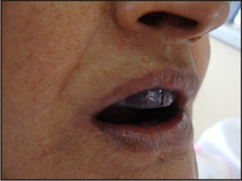
A 64 year old female patient reported to the department of prosthodontics with the chief complaint of loose dentures and wanted replacement of the same. Patient gave a history of missing teeth since last 10 years (Fig.1). On intraoral examination it was seen that both the maxillary and mandibular arches were completely edentulous and severely resorbed (Fig.2). Previous dentures were unstable and non-retentive. Patient was explained about the implant retained prosthesis but the patient refused for the option due to economical and age factor. Then it was decided to provide the conventional complete denture with the help of neutral zone impression technique. Informed consent was taken from the patient for the procedure.
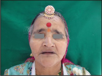 | Figure 1. Pretreatment photograph
 |
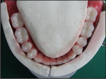
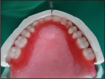
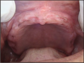 | Figure 2a Intraoral view showing atrophic maxillary and mandibular ridges.
|
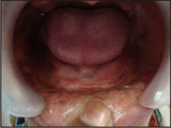 | Figure 2b. Intraoral view showing atrophic maxillary and mandibular ridges.
|
Clinical procedure:
i. Primary and Secondary Impressions
Primary impressions were made using irreversible hydrocolloid material i.e. alginate (Imprint,Bombay burmah ltd) and poured with plaster. Primary casts were prepared (Fig.3) and the custom trays were constructed with auto polymerising acrylic resin(DPI - RR, Bombay burmah ltd). Secondary impressions were made with low viscosity zinc oxide eugenol paste(DPI Impression paste) and master casts were poured.
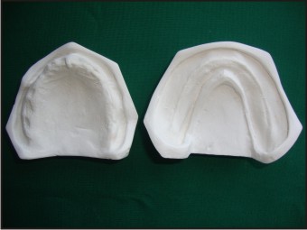 | Figure 3. Maxillary and Mandibular primary casts.
|
ii. Jaw Registration
The record base plates were fabricated in heat cure resin(DPI, Bombay burmah ltd) on master casts and assessed in patients mouth. Maxillary and mandibular occlusal rims were made. Conventional jaw relation was carried out in centric position and the occlusal rim casts were articulated on mean value articulator.
iii. Neutral Zone Impression
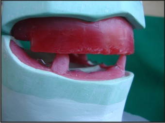
The mandibular occlusal wax rim was removed from the base plate and the acrylic stops were constructed, one in the anterior region and one on the both sides of the posterior region. Retentive wire loops were attached in the remaining areas of the base plate (Fig.4). Acrylic stops were used to preserve the vertical dimension and retentive loops to hold the impression material. A mixture of softened impression compound (Y-Dent, Delhi) and tracing greenstick compound (DPI, Pinnacle) in the ratio of 3:7 was attached to the lower base plate. The mandibular compound rim was adjusted at the same vertical height with maxillary rim on an articulator acts as a vertical stop. Patient was asked to sit in a comfortable, upright position with the head supported before making the impression. Softened mandibular compound rim was inserted into the patients mouth and asked to perform various functional movements like sucking, swallowing, smiling, pronouncing the letters such as ee, oo, etc., grining, licking (Fig.5). Any excess material above the usual height of the occlusal plane was removed with a sharp knife. The rim was resoftened and the procedure was repeated again. Now the maxillary occlusal wax rim was removed and the mixture of softened compound was adapted at the same vertical height with the mandibular rim maintaining the vertical stop. Maxillary compound rim was placed into the patient’s mouth and the same movements were performed for the upper arch. Both the compound rims were placed back on to the articulator and checked for the vertical dimension and centric relation (Fig.6).
 | Figure 4. Mandibular denture base with acrylic stops and retentive loops.
|
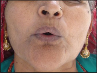 | Figure 5a. Functional movements performed by the patient.
|
 | Figure 5b. Functional movements performed by the patient.
|
 | Figure 5c. Functional movements performed by the patient.
|
 | Figure 5d. Functional movements performed by the patient.
|
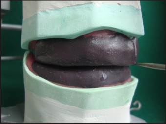 | Figure 6. Compound rims at determined jaw relation on an articulator.
|
Laboratory Procedure:
Locating grooves were cut on the master casts prior to the construction of matrices so that the matrices will fit back to the proper positions. With the lower compound rim in place, plaster matrices were made and lubricated on the lingual, labial and buccal side surrounding the compound rim (Fig.7a) These matrices were trimmed to their exact height of occlusal plane. The space within the matrices represents neutral zone and indicates the position of the artificial teeth. Similarly the plaster matrices were made on the labial and buccal side of the upper compound rim which indicates the outer limits of the neutral zone and serves as a guide for positioning the upper anterior teeth (Fig.7b).
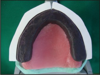 | Figure 7a Maxillary and mandibular matrices made of plaster surrounding the compound rim.
|
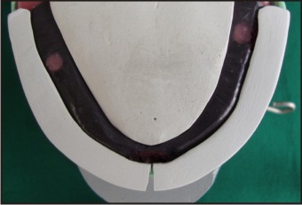 | Figure 7b Maxillary and mandibular matrices made of plaster surrounding the compound rim.
|
The compound occlusal rim were removed from the baseplate along with the wire loops and stops and replaced with the modelling wax rim. Artificial teeth were arranged exactly following the matrices (Fig.8a and 8b).
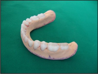
 | Figure 8a. Mandibular teeth arranged within the neutral zone.
|
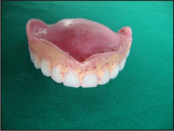
 | Figure 8b. Maxillary teeth arranged against the labial limits of the upper matrix.
|
Establishing the Polished surface:
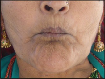
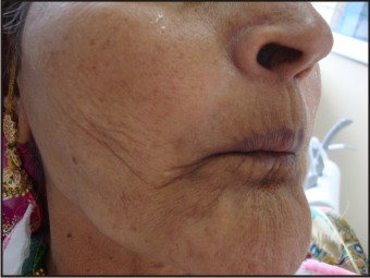
The trial dentures were checked for the esthetics, stability and retention in the patients mouth. Centric and vertical relationships were verified. The thickness, contours and shape of the polished surfaces of the dentures were recorded by means of a zinc oxide eugenol paste (Fig.9a and 9b). The excess material was trimmed away from the teeth. The trial dentures were flasked, processed and the final insertion was done (Fig.10).
 | Figure 9a. Impression of the polished surfaces of the upper and lower trial denture with zinc-oxide eugenol.
|
 | Figure 9b. Impression of the polished surfaces of the upper and lower trial denture with zinc-oxide eugenol.
|
 | Figure 10. Posttreatment photograph.
|
Discussion
Severely resorbed ridges can be managed by modifying the conventional procedures of fabricating a complete denture if other treatment options are restricted. Muscular forces are considered in this case during denture designing for improved stability and retention. A mixture of compound rim and green stick was used to record the neutral zone so that the rim can be sufficiently adapted and moulded by the surrounding structures[5]. Fish[8] described the three surfaces of the denture with each surface playing an independent and important role in the overall fit, stability and comfort of the dentures. In this case external surface was recorded by means of low viscosity zinc oxide eugenol paste. This tends to minimize the accumulation of food and allows proper shape and contour of the polished surfaces of the denture[9]. Positioning artificial teeth in the neutral zone will not interfere with the normal muscle function and the forces exerted by the musculature against the dentures are more favourable for retention and stability[1]. Even though there is extra clinical step involved in neutral zone technique the outcome of the denture will ensure good aesthetics, sufficient facial tissue support, more tongue space, retention and stabilization.
Conclusion
This technique dictates the correct positioning of the artificial teeth and arch form. Treating such complex cases is a challenge to most dentists. Thus, neutral zone technique can aid rather than confound our effects.
References
1. Victor E. Beresin and Frank J.Schiesser. The neutral zone in complete dentures. J. Prosthet. Dent. 1976; volume 36, no.4: 356-367.
2. Frank J. Schiesser. The neutral zone and polished surfaces in complete dentures. J. Prosthet. Dent. 1964; sept-oct, vol.14, no.5: 854-865.
3. Victor E. Beresin and Frank J.Schiesser. The neutral zone in complete dentures. J. Prosthet. Dent. 2006; feb, vol.95, no.2, 93-100.
4. The glossary of prosthodontics terms. J. Prosthet. Dent. 2005; July, 94(1):10-92.
5. David R. Cagna, Joseph J. Massad and Frank J. Schiesser. The neutral zone revisited : From historical concepts to modern application. J. Prosthet. Dent. 2009; 101: 405-412.
6. M.J Gahan and A.D.Walmslay. The neutral zone impression revisted. British Dental Journal 2005; 198: 269-272.
7. N.Brill, G.Tryde and R.Cantor. The dynamic nature of the lower denture. J. Prosthet. Dent.1965; may-june, vol15, no.3, 401-418.
8. Fish.E.W. Principles of Full Denture prosthesis, Ed.7, London, 1948, Staples press, Ltd.
9. J.F Walsh, T.Walsh. Muscle-formed complete mandibular dentures. J. Prosthet. Dent.1976; march, volume35, no.3, 254-258.
|