Part I - Diagnosis And Treatment Planning
Introduction:
As we progress, the myths of today become the truth of tomorrow. Practitioners of a scientific discipline are generally resistant to accept a new paradigm. Nonetheless a paradigm shift has occurred, a veritable explosion of new ideas and information has occurred, leading to rapid advances in the field.
New technological advances have helped the orthodontic profession progress in traditional and surgical methods of treatment. The profession has seen transitions from traditional braces to self-ligating braces, lingual brackets, removable aligners and more advanced technology, which have helped to address concerns that include but are not limited to better diagnostics, anchorage control, length of treatment and esthetics. An increase in the number of adult patients seeking orthodontic treatment and the need for a timely and efficient care will continue to drive technology and use of one beam computed tomography, miniscrews, piezocision, distraction osteogenesis and bioengineering[1]. Various technological advances that have graced the profession of Orthodontics in recent years include:
1. Diagnosis and treatment planning:
Diagnosis is the recognition and systematic designation of anomalies; the practical synthesis of the findings, permitting therapy to be planned and indication to be determined, thereby enabling the doctor to act[2].
Nowadays, the transition in diagnosis and treatment planning is towards the soft tissue paradigm, in which the primary goal of treatment is to obtain the best possible adaptation and proportions of the soft tissues in the face and mouth, and the secondary goal is functional dental occlusion[3].
The digital technology is no more a domain of a few now and this is the era of computers. Computer technology is expanding to include more areas in various scientific fields, and orthodontics is no exception. Orthodontists use computers for diagnosis, record keeping, practice management, patient evaluation, communication with colleagues and many other tasks[4].
Perhaps the most significant advance in orthodontic diagnosis for the new millennium is the use of 3-dimensional diagnosis. These programs produce superb results for photographs and cephalometric film or digital images and are rapidly becoming a primary diagnostic assessment. These advances in imaging are likely to enhance the accuracy and reliability of orthodontic diagnosis and treatment planning, and will be of importance in both clinical practice and research[4]. Recent advances in Orthodontic Diagnostic Aids include:
1. Digital study models:
Study models have long been an essential part of orthodontic process. They have traditionally been cast out of either plaster or stone and have served two main purposes to provide information for diagnosis and treatment planningand to provide a 3D record of the original malocclusion, any stages during correction and outcome of the treatment.Although study models are almost indispensable to orthodontist, because they are cast in plaster or stone, they do have a number of drawbacks in terms of storage and retrieval, diagnostic versatility, transferability and durability. The introduction of digital models (Fig 1) offers the orthodontist an alternative to plaster study models routinely used[5],[6].
 | Fig 1 : Digital Study Models
 |
Advantages:
1. Routinely, digital casts have great advantages over stone casts in the daily work of storage, viewing, and retrieval, and can be accessed at any time and at any distance for diagnostic, clinical, and information purposes.
2. Digital casts are fully calibrated so that the results are 1:1 with real life, even when they look bigger on the screen.
(c) The different features of indices of the OrthoCad software, such as the Bolton, Moyers, Tanaka, and arch length discrepancy analyses, can be useful in developing treatment plans. This process appears easier, less time-consuming, and has a reduced error of measurement, compared with conventional procedures on stone casts.
(d) The occlusogram, defining a color-coded scheme of the bite registration, including points of full contact on the digital casts, can be used for comparing different stages of treatment to determine the efficacy of the biomechanics.
(e) The measurement of the lower curve of Spee is more accurate on the digital casts, due to the possibility of drawing both lines and then calculating the distance between the deepest parts[7].
1. Digital Photography:
Photographs are an essential part of clinical documentation;the current practice is a full set of intra oral and extra oral photographs, both at start and completion of a course orthodontic treatment and ideally some mid-treatment photographs showing key stages of treatment.
Naturally, as has been with most things in our lives, technology has improved the way photography is done and the way we share our memories.Digital imaging, one of the hot fields in computer world, is attracting more and more orthodontists.
Digital photography (Fig 2) has been available since 1981. Advantages of digital photography includes immediate viewing, infrequent need for retakes, no film processing expenses, inexpensive storage, efficient retrieval from the computer, inexpensive and immediate duplication with no loss of quality and ability to transmit by modem through the internet[8].
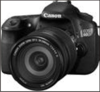 | Fig 2 : Digital Camera
|
Disadvantages:
1. Expensive hardware.
2. Diminished image quality (on improvement or alterations in image).
3. Difficulty in finding technical assistance.
4. Constantly improving hardware.
1. Digital Radiography:
Since its introduction in the 1980’s digital technology has become increasingly important to the practice of orthodontics. Computers have now taken over the role of tracking treatment progress, making appointments, recording digital photographs and analyzing cephalometric films. By eliminating paper charts they have paved the way for a paperless orthodontic office. For eg: Denoptix digital radiographic system[9].
Advantages of digital radiography (Fig 3) includes instantaneous image acquisition, facilitated image enhancement and archiving, elimination of technique sensitive image developing process and facilitated image sharing, no need of chemicals (dark room process), data manipulation on computer, ease of integration with patients photographs and other patient charts, ease of Storage, retrieval and transmission, faster in analysis and acquisition than conventional methods. Its disadvantages include high initial cost and digitizing may include errors such as head film movement and improper sequencing of digitized points.
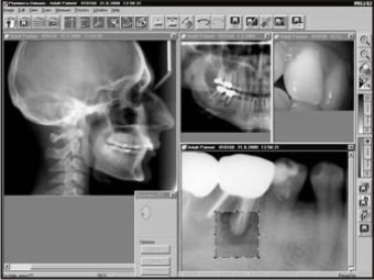 | Fig 3 : Digital Radiography
|
1. Digital Cephalometry:
Since its advent in 1931, conventional cephalometry has remained unchanged. Digital radiography has been accepted in dental community, but high cost delayed their progress. Recently with development of cost effective radiography (extra oral) and increased utilization of computers in orthodontics has made digital cephalometric imaging a viable option.
The paradigm shift is occurring in orthodontics from the widely accepted film based to digital cephalometry. A plethora of softwares are available to clinician to choose from like Vistadent, Dolphin, Quick ceph, Dentofacial planner, Vixwin software, Dr ceph, Ortho plan, Ceph x, Orthoview ceph etc. There are various factors to be considered before going to purchase software which includes facility of integration of photographs and study models, windows based system available, Dicom compatibility and lateral as well as posteroanterior analysis should be possible.
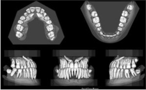
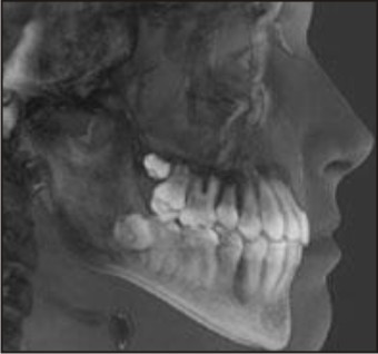
1. 3-D Facial Imaging:
The quest for accurate recording and representation of human facial features is an ancient art, not only in history and art, but also in orthodontics. 3-D facial imaging (Fig 4) is a complex and multifaceted field that is just entering mainstream clinical application.
 | Fig 4 : 3-d Facial Imaging
|
In 3-D medical imaging a set of anatomical data is collected using diagnostic imaging equipment. This data is then processed by a computer and displayed on a 2D monitor to give an illusion of depth. Depth perception causes this image to appear in 3D[12].
Applications of 3-D imaging:
• Pre and post orthodontic assessment of dental and skeletal relationships and facial aesthetics.
• Auditing Orthodontic outcomes with regard to soft and hard tissue.
• 3-D treatment planning.
• 3-D soft and hard tissue simulation.
• 3-D customized arch wires.
• Archiving 3-D facial, skeletal and dental planning for in treatment records.
• Research and medico legal purpose are also among benefits of 3-D models in orthodontics[13], [14].
1. CT Scan:
Conventional CT scan (Fig 5) was first developed by Sir Godfrey Hounsfield in 1967 and since the first prototype there has been a gradual evolution of five generations of such systems. Nevertheless, there are several limitations with these systems:
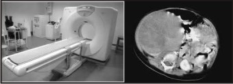 | Fig 5 : Computed Tomography
|
• Considerable physical space
• Much more expensive than conventional radiographic machines
• The images captured on detector are made up of multiple slices, which are stitched to obtain a final computer image, making it time consuming and less cost efficient.
• Radiation exposure to patients is responsible for imitating use of CT in complex craniofacial problems and specialized diagnostic information.
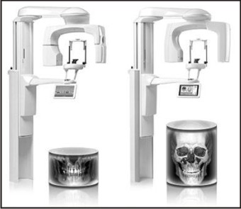
Craniofacial CBCT (Fig 6) were developed to counter some of the limitations of conventional CT scanning devices. In craniofacial CBCT the object to be evaluated is captured as the radiation falls onto a two dimensional retractor. This simple difference allows a single rotation of the radiation source to capture an entire region of interest as compared to conventional CT device where multiple slices are stalked to obtain a complete image. The cone beam also produces a more focused beam and considerable less scatter radiation compared to conventional fan shaped CT devices. This significantly increases x-ray utilization and reduces the x-ray tube capacity required for volumetric scanning. It is said that radiation exposure is 20% of conventional CT or equivalent to full mouth IOPA.
 | Fig 6 : Cone Beam Computed Tomography
|
Advantages of CBCT:
• Less expensive
• Smaller in size
• Exposure chamber (head) is custom built and reduces the amount of radiation
• Images are comparable to conventional CT and are displayed as full head view, as skull view or as regional components.
Applications of CBCT:
With CBCT, Orthodontists have many images that are not possible with conventional radiographic measures like impacted teeth and oral abnormalities, airway analysis, assessment of alveolar bone height and volume, TMJ morphology, lateral and frontal Cephalogram views, skeletal views, facial analysis, 3D review of dentition[15].
1. Magnetic Resonance Imaging:
Magnetic resonance imaging (Fig 7) was developed from knowledge gained in the study of nuclear magnetic resonance. In clinical practice, MRI is used to distinguish pathologic tissue (such as a brain tumor) from normal tissue. One advantage of an MRI scan is that it is harmless to the patient. It uses strong magnetic fields and non-ionizing radiation in the radio frequency range. Compare this to CT scans and traditional X-rays, which involve doses of ionizing radiation and may increase the chance of malignancy, especially in a fetus. While CT provides good spatial resolution (the ability to distinguish two structures an arbitrarily small distance from each other as separate), MRI provides comparable resolution with far better contrast resolution (the ability to distinguish the differences between two arbitrarily similar but not identical tissues)[12].
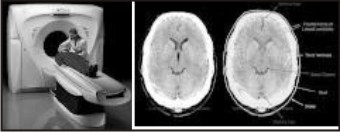 | Fig 7 : Magnetic Resonance Imaging
|
1. Digital Subtraction Radiography:
DSR required two identical images; the subtracted image is a composite of these two representing their different densities. In order to compare by subtraction technique the images must be recorded with a minimum degree of geometric distortion. Although visual examination of standard radiographs is unable to detect 0.85mm change in cortical bone thickness, this technique is so sensitive it can detect a 0.12mm change also. The ability of digital subtraction is to record minimum images is dependent on degree of matching of two images.
Applications:
• They can detect small osseous changes.
• Useful in diagnosis of dental, periodontal and carious lesions both of which are characterized by insidious and slow rate of progression.
• Used for quantitative estimation of mass or volume of a lesion.
• Absolute bone mass or volume changes can be measured using a reference wedge. Wedge may be continuous or a step wedge.
• System can measure upto 5% bone changes with greater than 90% accuracy.
• Contrast enhancement of image with colour has been suggested to aid in detection of small defects (periodontal).
• It has also been useful in detection of small changes in mandibular condyle position and integrity of articular surface and or osseous remodeling around granular hydroxyapatite implants.
• Assessing progress of periodontal therapy and failure of implants therapy[16].
1. Ultrasound (Ultrasonography):
The phenomenon perceived a sound is result of periodic changes in pressure in air against the eardrum. The periodicity of these changes lies anywhere between 1500 and 20000 cycles per second (hertz, Hz). By definition, ultrasound has a periodicity of greater than 20KHz. Diagnostic Ultrasonography (Fig 8), the clinical application of Ultrasound, employs vibratory frequency in range of 1 to 20 MHz.
Applications (in head and neck):
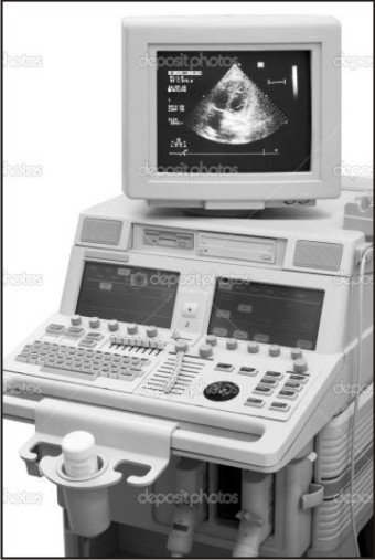 | Fig 8 : Ultrasonography
|
Mainly used in imaging of -
• Lymph nodes.
• Post surgery, oedema and hematoma.
• Eye, thyroid gland and parotid gland.
• Submandibular salivary gland.
• To demonstrate thickness of masticatory mucosa.
• Demonstrate displacement of soft tissue under denture by forces of occlusion[17].
1. Electromyography:
Electromyography (Fig 9) is defined as the recording and study of the intrinsic electrical properties of skeletal muscle by means of surface or needle electrodes, to determine merely whether the muscle is contracting or not; by insertion of a needle electrode into the muscle and observing by cathode-ray oscilloscope the action potentials spontaneously present in a muscle or induced by voluntary contractions, as a means of detecting the nature and location of motor unit lesions; or by recording the electrical activity evoked in a muscle by electrical stimulation of its nerve. Electromyograph is the instrument used in electromyography. Electromyogram is the record obtained by electromyography (EMG).
 | Fig 9 : Electromyography
|
The first effort to apply electromyography to dentistry was made by Robert E. Moyers. He observed that the normal relations of teeth to each other in the same jaw and with those of the opposite jaw were influenced by muscular balance.
With relevance to orthodontics, the muscles of importance are the[17]:
• Mandibular Elevators: Masseter muscle, Temporalis muscle, Medial Pterygoid muscle;
• Mandibular Depressor: Lateral Pterygoid muscle.
The Genioglossus muscle also plays an important role in determining facial morphology. This muscle is responsible for the protraction of the tongue.
Mentalis muscle and Orbicularis Oris muscle are also important[18].
1. Finite Element Modelling:
It is a technique of discrediting a continuum into simple geometric shapes elements, enforcing material properties and governing relationships on these elements giving due consideration to loading and boundary conditions which results in a set of equation, the solution which gives the approximate behavior of the continuum[19].
Advantage of Finite Element Method:
The finite element has been applied to numerous problems, both structural and nonstructural. This method has a number of advantages that have made it very popular.
This include the ability to -
• Model irregularly shaped bodies quite easily.
• Handle general load conditions without difficulty.
• Model bodies composed of several different materials because the element equations are evaluated individually.
• Handle unlimited numbers and kinds of boundary conditions.
• Vary the size of the elements to make it possible to use small elements where necessary.
• After the finite element model relatively easily and cheaply.
• Induce dynamic efforts
• Handle nonlinear behavior existing with large deformations and nonlinear materials.
1. Sure smile:
Sure smile (Fig 10) technique is the recent advancement in which computer management of 3D imaging of dentition is done followed by its manipulation into complex 3D data and robotics have resulted in new approach to treatment.
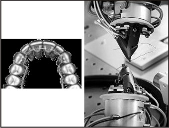 | Fig 10 : Sure Smile Technique
|
A patient centered practice is one that delivers high quality care with minimum amount of patient discomfort, compliance demand and chair time and completes treatment on time, in as short period as possible[20],[21].
Benefits of Sure Smile:
• Reduce errors in treatment resulting from appliance management
• It provides image capturing, 3D visualization of tools for diagnosis, monitoring, and patient communication along with precision appliances that can help the orthodontist to deliver truly customized care in a patient oriented practice.
Advantages of Sure Smile:
• Undesirable tooth movement may be reduced
• Arch wire selection errors may be reduced
• Bracket positioning errors may be reduced
• Bonding adhesive thickness errors can be reduced.
1. Rapid Prototyping:
Rapid prototyping, also known by other names such as additive fabrication and solid freeform fabrication, is the automatic construction of physical objects using additive processes including stereo lithography, selective laser sintering, and fused deposition modeling. The first techniques for rapid prototyping became available in the 1980s and were used to produce models and prototype parts. Today, they are used for a much wider range of applications and are even used to manufacture production quality parts in relatively small numbers.
The rapid prototyping model of teeth is initially used for the diagnosis and orthodontic treatment planning, and for communication with the patient and his parents for the impacted maxillary canines when compared with conventional radiography and CT scans. The use of rapid prototyping models seems to facilitate the surgical procedures and the communication with colleagues and patients. Surgery duration is reduced in 17% to 60% of patients, with fewer traumas, a more comfortable postoperative recovery, and fewer complications. Three dimensional modeling made possible the fabrication of the attachment for the canine traction. However, the main disadvantage in the use of this procedure is the exposure of the patient to CT radiation but the amount of radiation required has decreased as more advanced software and hardware technologies are developed [22].
1. Distraction Osteogenesis:
Distraction Osteogenesis (Fig 11), also called callus distraction, callotasis and osteodistraction is a surgical procedure used to reconstruct skeletal deformities and lengthen the long bones of the body. In 1989, a team of clincians led by Joseph McCarthy, MD (New York University Medical Center) performed the first distraction of the human mandible in an 18-month-old boy born with hemicraniofacial microsomia. Since the successful application of this technique to the human mandible, distraction osteogenesis has been used by clinicians to alter the shape and size of bones in the entire craniofacial skeleton. This technique for lengthening the mandible at the rate of 1 mm per day by gradual distraction of a bone callus was first introduced by orthopedic surgeons to correct length deficiencies of the long bones. . Using distraction osteogenesis, it is common to lengthen the mandible or move the midface and associated soft tissue from 10 mm to 20 mm in as many days. An important biological distinction between conventional orthognathic surgical techniques and distraction osteogenesis is the documented increase in volume of the associated soft tissues after bone distraction [23].
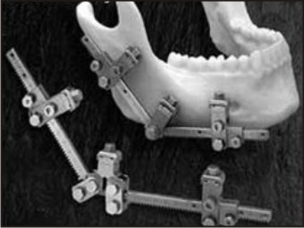 | Fig 11 : Distractors Used For Distraction Osteogenesis
|
This provides a clinical advantage over conventional surgery because it appears to be responsible for the minimal skeletal relapse observed after distraction. In addition, there is reduced morbidity, reduced need for bone grafts, and improved airway. The distraction procedure permits the correction of craniofacial deformity deformity to take place in early childhood, thus altering the patient's long-term treatment plan. The devices were broadly categorized based on direction of distraction and site of application. Recent development includes curvilinear distractors (mimic natural growth pattern in curvature); motorized and hydraulic distraction units with remote activation and monitoring can allow precise directional control and force control [24].
1. Mini Implants:
Kanomi et al in 1997[25] introduced smaller diameter mini or microscrew designed specifically for orthodontic use also known as temporary anchorage devices. Orthodontic miniscrews, often referred to as microscrews, temporary anchorage devices (TADs), orthodontic implants, or mini implants, provide us simpler alternatives to endosseous implants and onplants in orthodontics. Nowadays, mini-implants (Fig 12) are increasingly used as orthodontic anchorage sources as they provide a valuable alternative to extra-oral anchorage and offer several advantages. Their advantages include smaller size, minimal patient compliance, greater number of implant sites and indications, simpler placement procedure, immediate loading, no need for laboratory work, easier removal after treatment and lower cost[26].
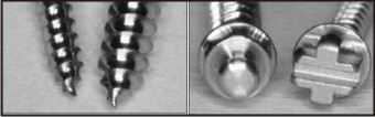 | Fig 12 : Mini Implants
|
1. Invisalign Braces:
In 1997, Chisti and Wirth applied 3-D computer imaging graphics to the field of orthodontics and created Align Technologies and the Invisalign method (Fig 13). Invisalign methods are great for people who do not have severe problems.
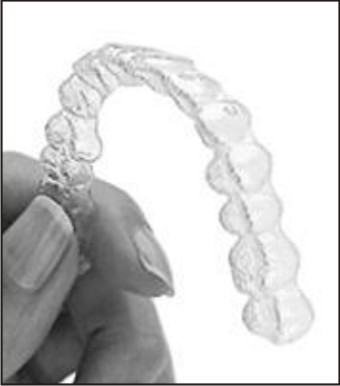 | Fig 13 : Invisalign
|
It is a series of clear plastic aligners that gradually achieve the same result of metal braces. The process of fitting invisible braces begins with a careful examination and creating model of teeth with the help of latest advances in 3-D computer technology. The system then generates a series of precisely customized aligners of irregular teeth. These braces are invisible, appeals to adults, no irritation to gums and they do not stain[27].
1. Relaxin:
Recent research is towards utilization of the power of a natural human hormone called relaxin to biochemically move teeth faster and less painfully during orthodontic treatment. Relaxin is a hormone that helps women's pelvic ligaments stretch in preparation for giving birth[28]. This ability prompted researchers to consider relaxin as a possible way to accelerate tooth movement and prevent relapse after orthodontic treatment. This painful and inconvenient problem led researchers to consider injecting relaxin into the gums to loosen the collagen and elastin fibers and reorganize them so teeth can move more freely into orthodontic alignment. Once the teeth have been moved, researchers will administer another injection of relaxin under the premise that it will further soften gum tissue fibers, preventing them from pulling teeth back into their original position[29].
1. Nanotechnology in orthodontics:
Micrometer sized dental nanorobots are constructed with specific motility mechanisms to crawl or swim through human tissues with navigational precision; acquire energy, sense and manipulate their surroundings; achieve safe cytopenetration and use any of a multitude of techniques to monitor, interrupt or alter nerve-impulse traffic in individual nerve cells. These nanorobotic functions may be controlled by an onboard nanocomputer that executes preprogrammed instructions in response to local sensor stimuli.
Orthodontic nanorobots (Fig 14) could directly manipulate the periodontal tissues, including gingivae, periodontal ligament, cementum and alveolar bone, allowing rapid and painless tooth movement. Orthodontic nanorobots could directly manipulate the periodontal tissues. Tooth straightening, rotating and vertical repositioning can be carried out within minutes to hours in contrast to current techniques, which require weeks or months to complete[30],[31].
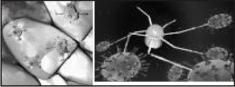 | Fig 14 : Orthodontic Nanorobot
|
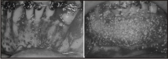
1. Wilckodontics:
In the past, corticotomies have been performed with the intent of inducing "blocks of bone movement" to accelerate orthodontic movement. Wilckodontics, also known as Accelerated Osteogenic Orthodontics (Fig 15) is the technique developed by Wilckos. It is similar to a single-tooth corticotomy, except that it is extended to all the teeth to be moved during orthodontic treatment. The procedure begins with comprehensive fixed orthodontic treatment, followed by buccal and lingual full-thickness flaps, then decortication of the alveolar bone cortical plates housing the teeth to be moved. A resorbable bone-graft augmentation is placed over the surgical site, and the soft-tissue flap is closed. Following the surgical procedure, orthodontic adjustments are made weekly and the cases were completed in approximately three or four months. The rate of tooth movement then returns to normal once the bone has sufficiently healed[32].
 | Fig 15 : Wilckodontics
|
Wilckodontics have several advantages that include shortened treatment time (3-4 times), decreased chance of root resorption following orthodontic therapy, increased alveolar bone which provides better support for teeth and facial profile, less likelihood for relapse, less discomfort associated with teeth movement compared to traditional orthodontics. The disadvantages include more expensive, mild risky invasive surgery, swelling and tenderness immediately after surgery, requires a recovery period for atleast one week.
1. Lasers:
Lasers (Fig 16) have been used in dentistry since 1960’s. More recently, the diode laser has been used in orthodontic practice because of cost-effectiveness, ease of use, positive patient response and impact on esthetic results. The diode lasers offer good hemostasis, reduced the potential for infection and prevented damage to teeth and bone as a result of its affinity for soft tissue only. As the popularity of this new technology increases, they can be used by orthodontists to perform cosmetic gingival contouring, exposure of teeth to facilitate eruption, frenectomy, gingivectomy, gingivoplasty, operculectomy, the removal of redundant tissue due to poor oral hygiene or space closure, removal of soft tissues to uncover temporary anchorage devices that were traditionally referred to other dental professionals[33].
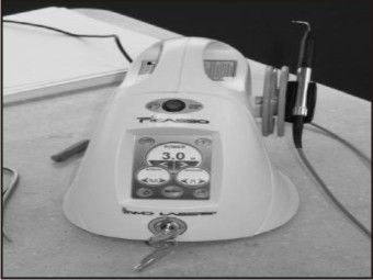 | Fig 16 : Soft Tissue Diode Laser Machine
|
Conclusion:
Advances in technology are changing the ways that patients experience dental treatment. Technology helps to decrease the treatment time and makes the treatment more comfortable for the patients.
References:
1. Bonnick AM, Nalbandian M, Siewe MS. Technological advances in nontraditional orthodontics. Dent Clin North Am 2011; 55(3): 571-584, ix.
2. Rakosi T, Jonas I, Graber TM. Color atlas of Orthodontic Diagnosis. 1st ed. Thieme; 1993.
3. Graber TM, Vanarsdall RL, Vig KWL.Orthodontics Current Principles and Techniques. 4thed. St. Louis: Mosby; 2009.
4. Bhalajhi SI. Orthodontics: The art and science. 3rd ed. New Delhi: Arya (Medi) Publishing House; 2003.
5. Reymond WR, Reymond WJ, Reymond MJ. Clinical implications of digital orthodontics. Am J Orthod Dentofacial Orthop 2000; 117: 240-241.
6. Redmond WR. Digital models: A new diagnostic tool. J Clin Orthod 2001; 35: 386 - 388.
7. Garino F, Garino GB. Comparison of dental arch measurements between stone and digital casts. World J Orthod 2002; 3(3): 250-254.
8. SandlerJ, MurrayA. Digital photography in orthodontics. J Orthod 2001; 28:197 - 202.
9. MeingJJ. The Denoptix digital radiographic system. J Clin Orthod 1999; 37: 407 - 411.
10. Forsyth D, Shaw WC, Richmond S. Digital imaging of Cephalometric radiography. Part 1: Advantages and limitations of digital imaging. Angle Orthod 1996; 66: 37 – 42.
11. Forsyth D, Shaw WC, Richmond S. Digital imaging of Cephalometric radiography. Part 2: Advantages and limitations of digital imaging. Angle Orthod 1996; 66: 37 – 42.
12. Quintero JC, Trosien A, Hatcher D, Kapila S. Craniofacial Imaging in Orthodontics:Historical Perspective, current status, and future developments. Angle Orthod 1999; 69:491-506.
13. Hajeer MJ, Ayoub AF, Siebert JP. Applications of 3-D imaging in orthodontics: part 1. J Orthod 2004; 31:62 - 70.
14. Hajeer MJ, Ayoub AF, Siebert JP. Applications of 3-D imaging in orthodontics: part 2. J Orthod 2004; 31:62 - 70.
15. Kau CH, Richmond S, Palomo JM, Hans MG. Three dimensional computed cone beam tomography in orthodontics. J Orthod 2005; 32:282 - 293.
16. Reddy MS, Jeffcoat MK. Digital subtraction radiography. Dent Clin North Am 1993; 37(4): 553-565.
17. Fikret S, Tulin A, Fulya I. Comparative data on facial morphology and muscle thickness using ultrasonography. Eur J Orthod 2005; 27: 562 – 567.
18. Iyer M, Valiathan A. Electromyography and its applications in orthodontics. Current science 2001; 80: 503 – 507.
19. Cattaneo PM, Dalstra M, Melsen B. The Finite element method: a tool to study orthodontic tooth movement. J DENT RES 2005; 84: 428-433
20. Sachdeva R. Sure smile technology in a patient centered orthodontic practice. J Clin Orthod 2001; 35: 245 – 253.
21. Mah J, Sachdeva R. Computer assisted orthodontic treatment: The sure smile process. Am J Orthod Dentofac Orthop 2001; 120: 85 – 87.
22. Faber J, Berto PM, Quaresma M. Rapid prototyping as a tool for diagnosis and treatment planning for maxillary canine impaction. Am J Orthod Dentofac Orthop 2006; 129(4): 583–5 89.
23. Grayson BH, Santiago PE. Distraction Osteogenesis. Semin Orthod 1999; 5(1): 1-2.
24. Grayson BH, Santiago PE. Distraction Osteogenesis. Semin Orthod 1999; 5(1): 64-73.
25. Kanomi R. Mini-implant for orthodontic anchorage. J Clin Orthod 1997; 31: 763-767.
26. Baumgaertel S, Razavi MR, Hansc MG. Mini-implant anchorage for the orthodontic practitioner. Am J Orthod Dentofacial Orthop 2008; 133: 621-627.
27. Wong B. Invisalign A to Z. Am J Orthod Dentofacial Orthop 2002; 121(5):540-541.
28. Definition of relaxin. www.medterms.com. Accessed 10, 2012.
29. Stewart DR, Sherick P, Kramer S, Breming P. Use of relaxin in orthodontics. Annals of New York Academy of sciences 2005; 1041(1): 379-387.
30. Saravana KR, Vijayalakshmi R. Nanotechnology in dentistry. Indian J Dent Res 2006; 17(2): 62-65
31. Freitas RA. Nanodentistry. J Am Dent Assoc 2000; 131(11): 1559-1565.
32. Owen AH. Accelerated invisalign treatment. J Clin Ortho 2001; 35(6): 381-385.
33. Burke B, Hamdan AM, Tufekci E, Shroff B, Best AM, Lindauer SJ. Perceptions of soft tissue laser use in orthodontics. Angle Orthod 2012; 82(1): 75-83.
|