Introduction:
The occlusal forces applied to a fixed partial denture are transmitted to the supporting structures through the pontic, connectors, and retainers. Factors that influence the longevity of a fixed partial denture and its abutment include occlusion, span length, bone loss, and quality of periodontium. Biomechanical factors such as overload, leverage, torque, and flexing induce abnormal stress concentration in a fixed partial denture. Stress concentration is found in the connectors of the prosthesis and in the cervical dentin area near the edentulous ridge[1].
Connectors, the portion of a fixed dental prosthesis that unites the retainer(s) and pontic are considered as heartthrob of abutments, since under occlusal load maximum stresses are concentrated on them. Selection of the right type of connector can make a real difference between success and failure. We are more accustomed to the use of rigid connector in clinical practice since its placement requires minimum technical and laboratory expertise[2].
But the real problem arises when we encounter a pier abutment[2]. Natural toothlocated between terminal abutments that serve to support a fixed orremovable dental prosthesis is known as pier abutment[3]. Restoration of 2 missing teeth and an intermediate pier abutment with a rigid fixed partial denture is not an ideal treatment. When an occlusal load is applied to the retainer on the abutment tooth at 1 end of afixed partial denture with a pier abutment, the pier abutment may act as a fulcrum. Thus, tensile forces may then be generated between the retainer and abutment at the other end of the restoration. Anterior or posterior abutments may experience extrusive forces during fulcrum action, and resultant tensile force at the retainer to abutment interface may result in potential loss of retention for these restorations[4].
It has been reported that rigid fixed partial dentures with pier abutments are associated with higher debonding rates than short-span prostheses. Thus, these restorations may result in marginal leakage and caries. Nonrigid connectors are suggested as a solutionto these difficulties[4].
The indications for the use of nonrigid connectorin fixed prosthodontics are[5]:
1. The existence of Pier abutment, which promote a fulcrum-like situation that can cause the weakest of the terminal abutments to fail and may cause the intrusion of the pier abutment.
2. The existence of the malaligned abutment, where parallel preparation might result in devitalisation. Such situation can be solved by the use of intracoronal attachments as connectors.
3. The presence of mobile teeth, which need to be splinted together with fixed prosthesis
4. Long span, fixed partial dentures which can be distort due to shrinkage and pull of porcelain on thin sections of framework and thus, affect the fitting of the prosthesis on the teeth.
The nonrigid connectors are mainly used to relieve stress on the abutment and to accommodate malaligned fixed partial denture.
The four types of nonrigid connectors are the:
1. Dovetail(key-keyway) or Tenon-Mortise typeconnectors.
2. Cross-pin and wing type connector.
3. Split typeconnector.
4. Loop type connector.
This clinical report describes the prosthodontic management of an edentulous span on both sides of a pier abutment, with fixed partial denture having anon-rigid connector.
Case Report
A 40 year old female patient was referred to the Department of prosthodontics, Career Post Graduate Institue of Dental Sciences and Hospital, Lucknow with the chief complaint of inability to masticateandunpleasant aesthetics. The intraoral examination revealed missing maxillary right first premolar and first molar. Intra oral periapical radiograph showed good bone support for all the teeth to be used as abutment. The treatment options available to the patients were:
a. Implant in edentulous spaces.
b. Fixed partial denture with rigid connector.
c. Fixed partial denture with non-rigid connector.
The patient did not agree for the implant due to surgical intervention and financial constrains. The treatment of the patient with Fixed Partial Denture with rigid connector would have resulted in detrimental effect on abutments as well as the final prosthesis.
Hence, it was decided to do restoration with fixed partial denture with nonrigid connector of Tenon-Mortise type.
Technique
Step by step procedure:
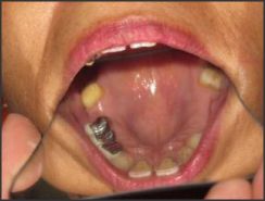
1. The tooth preparation of canine, second premolar and molar was done for metal-ceramic fixed partial denture with buccal facing ceramic and non-rigid connector between the second premolar and first molar. The distal of the second premolar was prepared to accommodate anon-rigid connector (Fig I).
2. Putty-wash impression (Aquasil, Dentsply) was made for the preparation of the working model. It was poured in high-strength die stone (Kalabhai Karson Pvt.Ltd.).
3. Provisional restoration was cemented.
4. Fixed partial denture with non-rigid connector was prepared. First, the anterior segment of canine, first premolar and second premolar with the keyway (Mortise) on its distal aspect was fabricated. Then the second and the first molars with key (Tenon) on its mesial aspect was fabricated in wax and then cast (Fig. II & III).
5. Accurate alignment of mortise is crucial, it must be parallel to path of placement of distal retainer. This is accomplished with a dental surveyor.
6. After casting, metal try-in of the individual units were done to verify proper seating. Then ceramic facing was added (Fig. IV).
7. At the time of cementation, mesial segment was placed first followed by cementation of distal segment (Fig V, VI & VII).
Discussion
Non-rigid connector provides the opportunity to provide the break type of connection in fixed partial denture. There is a conflicting opinion on where to place the non-rigid connector. Markley[6] suggested placement on one of the terminal abutments and not at the pier abutment. Adams[7] suggested placing the connector at the distal side of pier, and if
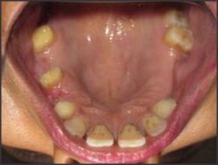 | Fig I Distal end of the second premolar prepared
 |
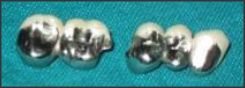 | Fig II Mesial segment with mortise(keyway) and distal segment with tenon(key)
|
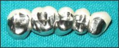 | Fig III Mesial and distal segment joined.
|
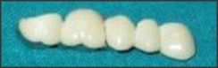 | Fig IV Ceramic facing of the prosthesis.
|
 | Fig V Mesial unit first cemented on the prepared teeth
|
 | Fig VI Distal unit cemented later.
|
 | Fig VII Post operative
|
desired, adding one more at the distal side of the anterior retainer, while Gill[8] suggested placing it at one side or both sides of the pier.
Carl E.Misch[9] recommended that in conventional fixed prostheses, the "male" portion of a nonrigid attachment usually is located on the mesial aspect of the posterior pontic, whereas the "female" portion is in the distal aspect of the natural pier abutment tooth. This prevents mesial drift from unseating the attachment. However, an implant does not undergo mesial drifting, and the non-rigid connector location is more flexible. For a natural pier abutment between two implants, a stress breaker is not indicated.
In this case report, the nonrigid connector was placed on the distal side of the pier abutment which was beneficial. Since the long axis of the posterior teeth usually leans slightly in a mesial direction, vertically applied occlusal forces produce further movement in this direction. This would nullify the fulcrum effect and the patrix/male of the attachment would be seated firmly in place when pressure is applied distally to the pier. Shillingberg[10] suggested placing the connector at the distal aspect of pier abutment.This position was also supported by finite element analysis study done by Oruc et al[4].
The contraindications of using a non-rigid connector in a posterior 5-unit fixed partial denturewith a pier are as follows:
1. Significant mobility of abutments.
2. If the span between the abutments is longer than one tooth.
3. If the distal retainer and pontic are opposed by a removable partial denture or an edentulous ridge, while the two anterior retainers are opposed by natural dentition, allowing the distal terminal abutment to supraerupt.
Conclusion
The paper describes a technique to neutralize the effect of forces that are transmitted to terminal abutments when a rigidly designed fixed partial denturewith an intermediate pier abutment acts as a fulcrum resulting in damage to abutment teeth. The selection of right type of connector is an important step when sorting treatment plan.
References
1. Non-rigid Connectors in Fixed Dental Prosthesis - A Case Report SP Dange , AN Khalikar , Shiv Kumar. JIDA Nov 2008;2(11):356.
2. Non-rigid connector: The wand to allay the stresses on abutment. Saurav Banerjee, Arlingstone Khongshei, Tapas Gupta, and Ardhendu Banerjee Contemp Clin Dent. 2011 Oct-Dec; 2(4): 351-354.
3. Glossary of prosthodontic terms. 8
4. Stress analysis of effects of nonrigid connectors on fixed partial dentures with pier abutments Selcuk Oruc, Oguz Eraslan, H. AlperTukay and Arzu Atay. J Prosthet Dent 2008;99:185-192).
5. Non-rigid connectors in fixed prosthodontics: current concepts with a case report. P.V.Badwaik, A.J.Pakwan. JIPS, June 2005;5(2):99-102.
6. Broken-stress principle and design in fixed bridge prosthesis. Markley MR. J Prosthet Dent.1951;1:416-23.
7. Planning posterior bridges. Adams JD .J Am Dent Assoc. 1956;53:647-54.
8. Treatment planning for mouth rehabilitation. Gill JR. J Prosthet Dent. 1952;2:230-45.
9. Dental implant prosthetics. Elsevier Mosby. Carl E.Misch.2005; Pg:189-190.
10. Fundamentals of fixed prosthodontics. 3rd ed. Chicago: Quintessence; Shillingburg HT, Jr, Hobo S, Whitsett LD, Jacobi R, Brackett SE;1997;Pg:85-118. |