Introduction:
In the past, the best clinical results were achieved by Orthodontists who had the best wire bending skills. However, "The best results in the present and in future will be achieved by those orthodontists who are best at accurate bracket positioning"
Because of the increased difficulty in accurate bracket placement in private practise, accurate bracket placement is of the utmost importance and is greatly facilitated by an indirect bonding technique.
The technique was introduced by Silverman and Cohen in the early 1970s,[1],[2],[3] but many variations have been developed, using conventional dental composites,[4] commercial adhesives,[5] or unconventional adhesives [6],[7] to attach the bracket to the working cast. In most of the indirect bonding technique the adhesives must be removed from the bracket mesh with running water, an ultrasonic cleaner and acetone, or a tooth brush before the bonding resin is applied and the bracket are bonded to the teeth. [8],[9],[10],[11],[12],[13].
The technique described is a modification of a method reported by Dr Rajgopal[14]. In this article we have also accessed the accuracy of indirect bonding versus direct bonding technique.
The method illustrated here uses readily available materials and leaves an adhesive free mesh prior to bonding. The patient shown had a class I bimaxillary protrusion with anterior spacing. Brackets were .022'' PEA (MBT PRESCRIPTION). The right quadrant U/L were selected for indirect bonding and left side for direct bonding procedure.
Procedure
1. Mark vertical and horizontal lines on the working cast for bracket placement. (Fig 1)
2. Spread out a 10mm strip of micropore adhesive tape on a glass plate with the adhesive side up. Place the brackets on the tape. Cut out the tape around each bracket. (Fig 2)
3. Apply a drop of cyanoacrylate glue to the non adhesive side of each piece of micropore tape. (Fig 3)
4. Affix the brackets to the cast in the prescribed position (Fig 4). Gelatin Jigs prepared over brackets for additional retention and to prevent inadvertent debonding during bonding procedure
5. Place the casts in vaccum forming machine and fabricate a transfer tray using 2mm thickness of bioplast. (Fig 5)
6. Remove the tray from the cast. The micropore tape will adhere to the cast because of the strong bond of the glue. The bracket with the adhesive free mesh will be embedded in the transfer tray material.(Fig 6a, 6b)
7. Etch the patient teeth with 37%phosphoric acid for 15 seconds.
8. Apply primer over the etched tooth surface and cure it with light cure for 10 seconds (3M transbond primers)
9. Now apply adhesive paste to bracket base and position the transfer trays in the mouth and cure each bracket for 40 seconds(10 seconds on each side) .(fig 7a, 7b)
10. For easy removal ask patient to gargle with warm water and then give cuts in the interdental area of the transfer tray using scissor and peel the tray from the lingual and chech the bracket positions.
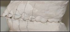 | Fig 1: long axes and bracket slot heights scribed on working cast.
 |
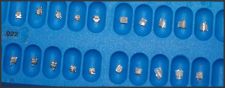 | Fig 2: Bracket affixed to adhesive side of tape to right side quadrant and left side without adhesive tape for direct bonding
|
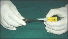 | Fig 3: Bracket affixed with cyanoacrylate glue on the nonadhesive side of tape for bonding
|
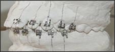 | Fig 4: Bracket placed on cast
|
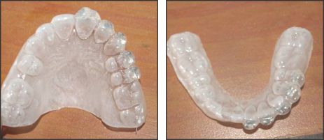 | Fig 6 & 6a: brackets free mesh embedded in tray material
|
 | Fig 7 & 7a: tray positioned in mouth
|
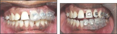
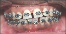 | Fig 8: Patient after indirect bonding and direct bonding procedure
|
The (Fig 8) shows patient after indirect bonding and direct bonding procedures and (Fig 9) after debonding procedure. The initial OPG and Lateral Ceph are shown in (Fig 10a,10b) and after debonding OPG and Lateral Ceph are shown in (Fig 11a, 11b).
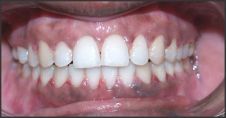 | Fig 9: Patient after debonding procedure
|
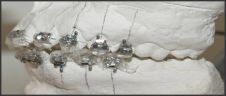 | Fig 5: Gelatin Jigs prepared over brackets for additional retention and to prevent inadvertent debonding during tray removal procedure
|
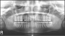 | Fig 10: Initial OPG
|
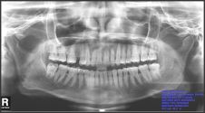 | Fig 11: After Debonding OPG
|
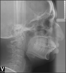 | Fig 12: Initial Lateral Ceph
|
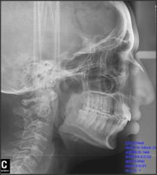 | Fig 13: Lateral Ceph After Debonding
|
Discussion:
Comparision of direct with the indirect bonding:
In this study we have done indirect bonding in right quadrants and direct in left quadrants. The treatment results suggest that there is no difference between direct and indirect bonding. In vitro shear bond strength comparison between direct and indirect-bonded attachments showed no significant difference between the two groups [16]. Bond strength obtained with Thomas indirect bonding technique was comparable with direct bonding technique. Also the time consuming for indirect bonding is less comparable to direct , with increased patient comfort and good technical and clinical advantages[15] . Especially during the first 4 months after brackets placement, this indirect bonding protocol allowed for significant reduction in plaque accumulation around the braces and reduced onset of white spots during the orthodontic treatment[17]. Comparisons of the microleakage scores between the direct and the indirect bonding groups at the enamel-composite and composite-bracket interfaces indicated no statistically significant microleakage differences at the gingival and occlusal margins (P > 0.05). The type of bonding method (direct versus indirect) did not significantly affect the amount of microleakage at the enamel-composite-bracket complex[18].
The advantages of this technique with the technique of those described by Dr Rajgopal
1) Indivisual jigs prepared for each tooth which offers better strength and stability during bonding procedure
2) Less chance of debonding during tray removal
3) Jigs can later used to rebonding in case of bracket debonding.
4) Easy to prepare jigs and cost effective procedure
5) Less time consuming
6) This procedure can also be used in lingual orthodontic bonding procedure
The discrepancy introduced by the thickness of the micropore tape
First order discrepancy introduced by the thickness of the micropore and a small drop of low - viscosity cyanoacrylate glue would be minimal and , in any event, would be the same thickness and is well adapted to the cast, it will not alter the torque value of the brackets[14]. Furthermore, the adhesive of the Micropore tape does not clog the bracket mesh and therefore does not require a time-consuming cleaning procedure.
Conclusion:
Indirect bonding is considered to be a useful and efficient approach that improves the results of the treatment. Success with the technique requires attention to detail, but does not require excessive complexity. Thus the above mentioned technique is as simple accurate and cost effective indirect bonding procedure. Continuous improvement in clinical results can be accomplished by assessing finished treatment and by using that knowledge for the benefit of future patients.
References:
1. Gottlied E.L. Mortan Cohen and Elliott Silverman on indirect bonding practice. J Clinic Orthod. 1974; 8: 384-04.
2. Elliott Silverman, Morton Cohen. A Report On Major Improvements In The Indirect Bonding Technique, J Clin Orthod. 1975;9:270-76.
3. Elliott Silverman, Morton Cohen. The Twenty-Minute Full Strap Up. J Clin Orthod. 1976;10:764-68.
4. Royce G Thomas. Indirect Bonding Simplicity In Action. J Clin Orthod. 1979;13:93-06.
5. Larry W White. A New and Improved Indirect Bonding Technique. J Clin Orthod. 1999;33:17-23.
6. Michael D Simmons. Improved Laboratory Procedure For Indirect Bonding Of Attachments. J Clin Orthod. 1978;12:300-02.
7. Kenneth H Fried, George V Newman. Indirect Bonding With a No-Mix Adhesive. J Clin Orthod. 1983;17:414-19.
8. George V Newman. Direct And Indirect Bonding Of Brackets. J Clin Orthod.1974;8: 264-72.
9. Farhad Moshiri, Micheal D Hayard. Improved Laboratory Procedure For Indirect Bonding. J Clin Orthod. 1979;13:472-73.
10. Robert P Scholz. Indirect Bonding Revisited. J Clin Orthod. 1983;17:529-36.
11. Ronald B Cooper, Nile A Sorenson. Indirect Bonding With Adhesive Precoated Brackets. J Clin Orthod. 1993;27:164-67.
12. John H Hichman. Predictable Indirect Bonding. J Clin Orthod. 1993;13:215-17.
13. Elliott M Moskowitz, L Douglas Knight, John J Sheridan, Timothy Esmay, Kruno Tovilo. A New Look Of Indirect Bonding, J Clin Orthod. 1996;30:277-81.
14. R Rajagopal, A Vankatesan, K Gnanashanmugham, S Harish Babu. A New Indirect Bonding Technique. J Clin Orthod. 2004;38:600-02.
15. John T. Kalange. Indirect Bonding: A Comprehensive Review of the Advantages. World J Orthod. 2004;5:301-07.
16. Swetha M, Pai VS, Sanjay N, Nandini S. Indirect versus direct bonding--a shear bond strength comparison: an in vitro study. J Contemp Dent Pract. 2011;12(4):232-38.
17. Domenico Dalessandri, Michela Dalessandri, Stefano Bonetti, Luca Visconti, Corrado Paganelli . Effectiveness of an indirect bonding technique in reducing plaque accumulation around braces. Angle Orthod. 2012 ;82:313-18.
18. Yagci A, Uysal T, Ulker M, Ramoglu SI. Microleakage under orthodontic brackets bonded with the custom base indirect bonding technique. Eur J Orthod. 2010 ;32(3):259-63 |