Introduction:
The various treatment options available for the replacement of teeth for partially edentulous patients include removable prosthesis, fixed prosthesis and implant supported prosthesis. Some patients who are given choice between an implant supported prosthesis and RPD, are not able to pursue the implant care leading to higher demand of RPD1. Also, in cases where the fixed prosthesis is not advised as in distal extension cases, long span edentulous area with excessive bone loss and cases of requirement of cross-arch stabilization, RPD can be easily planned as a treatment modality11. Thus, RPD had always been the most used treatment modality.
Being the most used treatment modality, the main drawback is lack in proper planning and designing of RPD. The conventional RPD that is generally provided in daily practice is basically “gum stripper” which causes undue forces over teeth and supporting tissues. Thus, only a properly planned RPD can only provide a prosthesis that is comfortable and stable in function and socially acceptable in appearance1. There are many systems present to classify RPD. The most widely used method of classification is KENNEDY-APPLEGATE classification1,11. i.e.
1) CLASS I: bilateral edentulous area located posterior to remaining natural teeth.
2) CLASS II: unilateral edentulous area located posterior to remaining natural teeth.
3) CLASS III: unilateral edentulous area with natural teeth both anterior and posterior to it.
4) CLASS IV: single, bilateral edentulous area located anterior to remaining teeth.
5) CLASS V: Edentulous area bounded anteriorly and posteriorly by natural teeth but anterior abutment is not suitable for support.
6) CLASS VI: Edentulous area in which teeth adjacent to space are capable of total support.
 |
 |
The simplest method is according to support; it is receiving from the dental arch as
1) TOOTH-SUPPORTED i.e. CLASS III,
2) TOOTH-TISSUE-SUPPORTED i.e. CLASS IV
3) TISSUE-SUPPORTED i.e. CLASS I AND II prosthesis.
The designing of RPD varies according to type of support and also it is easier for a dentist to convey the information to lab when some method of classification is present. To understand the designing of RPD, knowledge of various components is must. The various components of RPD1,2,11 are:
MAJOR CONNECTOR
MINOR CONNECTOR
REST AND REST SEAT
DIRECT RETAINER
INDIRECT RETAINER
Denture Base And Replacement Teeth Major Connector:
it unifies all the parts of prosthesis and distributes the applied force throughout the arch. It must be rigid to distribute forces and must end away from gingival margin to avoid impingement with free gingival margin. In case of maxillary major connector, it should end 6mm away from gingival margin and in case of mandibular major connector, this distance should be 3mm. The borders of connector should be beaded to prevent food entrapment1,11. Planned relief should be given under major connector.
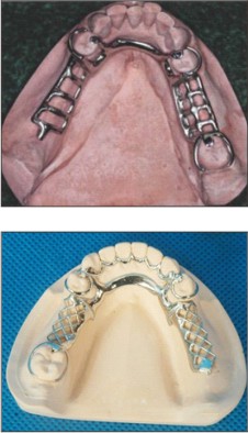
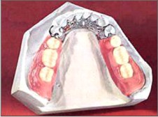
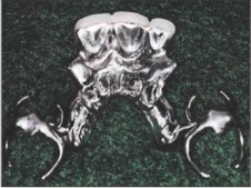
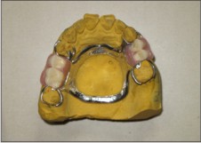
The various maxillary major connectors are:
1. SINGLE POSTERIOR PALATAL BAR is generally used as interim partial denture.
 |
|
2. PALATAL STRAP is indicated in tooth supported partial dentures and in bilateral distal extension cases of short span. The width of strap increases as the edentulous span increases.
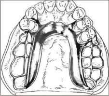
3. HORSE-SHOE SHAPED is mainly used in cases of replacement of anterior teeth and posteriorly extending inoperable tori. It is least favorable connector as it lacks rigidity.
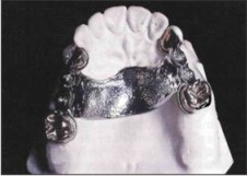
4. ANTERO-POSTERIOR PALATAL STRAP is indicated in distal extension cases, replacement of anterior teeth is there and presence of palatal torus is there.
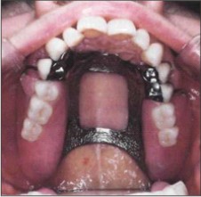
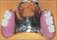
5. COMPLETE PALATE is used in long span distal extension cases and when periodontal support of teeth is weak.
The various mandibular major connectors are:
1. LINGUOBAR used in tooth supported RPD and when sufficient space is there between gingival margin and floor of mouth.
2. LINGUOPLATE indicated in long span distal extension cases, periodontally weak teeth and when the depth of the floor of mouth is less.
3. DOUBLE LINGUAL BAR is needed when anterior teeth have reduced periodontal support and large interproximal spaces are there that lead to unaesthetic appearance.
4. LABIAL BAR is indicated when lingual inclination of teeth prevent placement of conventional lingual bar.
5. SUBLINGUAL BAR is advised when there is inadequate space for lingual bar.
Minor Connector: its primary function is to join the other units of prosthesis to major connector which leads to distribution of stresses1,11. It should have sufficient bulk to resist forces and should be located in tooth embrasure with its thickest portion is toward lingual side, gradually tapering towards the contact area9.
It may be in the form of mesh work or lattice work or bead form. The mandibular connector should be extended to 2/3rd of the length of edentulous ridge and maxillary connector should extend till the entire length of ridge to cover the tuberosity. Relief should be given under the minor connector when they cross the gingival margin.
Rest And Rest Seat:
It provides the vertical tooth support and direct and distribute occlusal forces to the abutment teeth. According to the surface on which rest seat is prepared, it can be occlusal rest, incisal rest and lingual rest1,11.
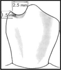
Occlusal Rest:
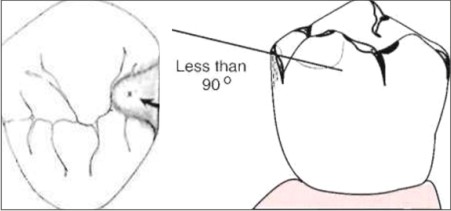
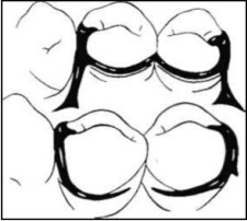
It can be prepared on sound enamel, in crowns and inlays and in restorations like amalgam. The rest seat is rounded triangular shaped with apex towards the centre of occlusal surface. The rest seat is spoon shaped with smooth gentle curves. The size of rest seat should be 1/3-1/2 of mesiodistal diameter and 1/2 of buccolingual width4,10. The angle formed between the occlusal rest and vertical minor connector should be less than 900 so that occlusal forces are directed along the long axis of abutment.
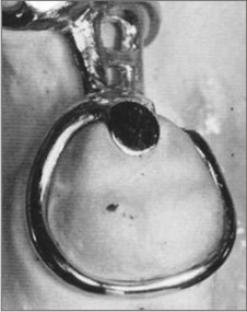
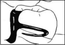
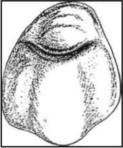
LINGUAL REST and INCISAL REST are prepared over lingual and incisal surfaces of tooth.
 | Lingual Rest
|
 | Incisal Rest
|
Direct Retainer:
It engages the abutment teeth to resist displacement of prosthesis away from the basal seat tissue. The retention is obtained by the frictional means by engaging the tooth undercut. The amount of retention provided by direct retainer depends on:
Tooth contour: more is the angle of cervical convergence, causes the placement of clasp terminal near the height of contour.
Flexibility of clasp arm1:
The more is the length of clasp arm, more is the flexibility.
More is the diameter of clasp arm, less is the flexibility.
Round cross-section clasp arm is universally flexible form.
Flexibility is proportional to bulk of material of clasp arm. Thus, its better to use cobalt-chromium alloys as greater rigidity with less bulk is possible.
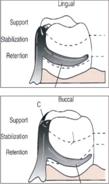
The clasp assembly has 2 clasp arms i.e. Retentive arm which engages gingival 1/3rd of the tooth and Reciprocal arm which engages middle 1/3rd of the tooth6,7.
The part of clasp must be placed below the height of contour of abutment tooth to get the retention for RPD because clasp retention comes from resistance of metal to deformation when dislodging forces are applied.
Extracoronal retainers i.e. clasps are classified into 2 basic categories i.e.
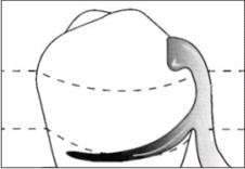
1. Circumferential clasp: approaches the retentive undercut from occlusal direction
2. Bar clasp: approaches the retentive undercut from gingival direction.
The circumferential clasp is of following types:
i) Simple Circlet Clasp:most versatile and widely used clasp. Mainly indicated on tooth supported RPD where mesiobuccal undercut is present11.
ii) Reverse circlet Clasp:mainly used in distal extension partial denture cases where undercut is adjacent to edentulous space.
iii) Multiple Circlet Clasp:two simple circlet clasps joined at the terminal end of two reciprocal arms. It is mainly used when principal abutment is weak periodontally1,11.
iv) Embrasure Clasp:two simple circlet clasps joined at the body. It is most frequently used on dentulous side.
v) Ring Clasp:mostly indicated on tipped molars.
vi) Hairpin Clasp:simple 'C'clasp in which retentive arm after crossing the facial surface of tooth from its point of origin loops back in hairpin turn to engage proximal undercut below its point of origin.
vii) Onlay Clasp:it is an extended occlusal rest with buccal and lingual clasp arms. Indicated in cases where occlusal surface of abutment is below the occlusal plane.
viii)Combination Clasp:it consists of wrought wire retentive arm and cast reciprocal arm. Indicated on tooth adjacent to distal extension space when the usable undercut on tooth is on mesiobuccal surface.
The amount of retention should always kept minimum to resist dislodging forces. Also, more than 1800 of tooth surface should be covered by clasp assembly7. The clasp assembly should provide at least 3 point contact with the tooth i.e. occlusal rest, retentive clasp terminal area and reciprocal arm terminal area1.
Indirect Retainer: it is mainly used in distal extension partial denture cases that prevent the movement of denture base away from the tissues. It should be placed as far as possible to distal extension denture base (mostly on mesial fossa of 1st premolar) to obtain best leverage advantage against dislodgement1,8,11.
By taking the preview of information about RPD, now proceed with the patient. the partial denture service is logically divided into 6 phases1 i.e.
 |
|
Phase 1 : Patient Education
Phase 2 : Diagnosis And Treatment Planning, Surveying, Mouth Preparation And Then Designing
Phase 3 : Adequate Support For Distal Extentsion Cases.
Phase 4 : Harmonius Occlusion Verification
Phase 5 : Initial Placement Procedure
Phase 6 : Preiodic Recall
Phase 1 : PATIENT EDUCATION: it should begin at initial contact with patient and will continue throughout the treatment. It includes the motivation of patient for better oral hygiene maintenance. Patient must be made to understand the need of RPD specifically for the patient.
Phase 2: DIAGNOSIS AND TREATMENT PLANNING: a logical and properly sequenced treatment plan is essential for successful treatment of patient because many failures in RPD are because of inadequate diagnosis and inappropriate treatment plan. It includes:
i) PATIENT INTERVIEW: The patient should be asked about his chief complain and expectations from prosthesis, and about any past medical history that will have effect on the treatment outcome11.
ii) ORAL EXAMINATION: it should be done in sequential manner11 i.e.
Visual Examination: it will detect the signs of dental diseases.
Note for the teeth that are carious lesion and periodontal problem.
The number of teeth remaining, location of edentulous area and quality of residual ridge must be noted as they have definite bearing on the proportionate amount of support.
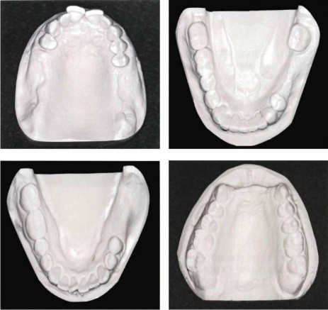
iii) DIAGNOSTIC CASTS: these are used to supplement oral examination1. it helps in
Determination of teeth location, contour and occlusal plane relationship.
Determination of residual ridge contour and size of ridge.
Permit the view of occlusion from both the lingual and buccal aspects.
Used as a constant reference as the work progresses and as a permanent patient record after the treatment.
The diagnostic casts are then mounted on an articulator to make the occlusal analysis.
 |
|
iv) RADIOGRAPHS: The objectives of a radiographic examination1 are
to locate areas of infection and other pathosis, root fragments and bone spicules that may be present;
to display the presence and extent of caries and evaluation of periodontal conditions ;
to evaluate the alveolar support of abutment teeth, their number, the supporting length and morphology of their roots.
Surveying: The primary purpose is to identify the modifications of oral structures that are necessary to fabricate a RPD which will lead to good prognosis. The basic aim of surveying is to identify one path of insertion without interferences then only a RPD can be retentive. For this, guide planes are created. The procedure recommended for surveying is3:
1. Position the diagnostic cast onto the surveyor table so the occlusal plane is parallel to the base of the surveyor stand.
2. Adjust the antero-posterior tilt of the cast by placing the analyzing rod against the proximal tooth surfaces adjacent to the edentulous spaces. Change the tilt of the surveyor table until maximum parallelism of the proximal surfaces has been attained.
3. Vary the lateral tilt of the cast (without altering the antero-posterior tilt) until the recesses of the abutment teeth that are to receive the clasp tips are approximately equal.
4. Continue by evaluating the hard and soft tissue prominences and corresponding recesses that may interfere with insertion or removal of rigid portions of the metal framework
5. Consider the aesthetic requirements, particularly if anterior replacement teeth are necessary.
6. After the orientation is established, mark the height of hard and soft tissue contours on the casts with a carbon marker.
7. Tripod the diagnostic cast which allows one to replace the cast on the surveyor in the same position at any subsequent time.
8. Draw the formal design of the RPD framework on the diagnostic cast.
Guide Plane: proximal tooth surfaces that bear parallel relation to each other act as guide plane. The prosthesis can be placed and removed without strain on teeth contacted and without damage to underlying soft tissue as one path of insertion or removal is obtained.10
Mouth Prepparation: it is fundamental to successful treatment outcome as mouth has to be prepared before to receive prosthesis. It includes:
General Mouth Preparation: all teeth causing pain or discomfort have to be treated first. It includes: oral surgical preparation, periodontal preparation and restorative preparation.
Specific Mouth Preparation10:
1. PREPARATION OF GUIDE PLANE: they are prepared on the proximal surface of abutment teeth so that one path of insertion or removal can be obtained.
2. All the interferences while the placement or removal of prosthesis should be removed.
3. Amount of undercut can be varied by altering the tooth contours (by varying the angle of convergence) which leads to change in amount of retention.
4. REST SEAT PREPARATION: It must always be done after the preparation of guide planes. The rest seat should be well rounded so that no premature contact and stress concentration occurs in that area. Preparation of rest seat is done according to the type of rest chosen for designing i.e. occlusal, incisal or lingual rest.
Designing Of Partial Denture1,4,11:
The designing of RPD varies according to the type of support it obtains. i.e.
Free end saddle type ( CLASS I AND II)
Bonded saddle type (CLASS III)
FREE END SADDLE CASES: in these cases, support is mainly derived from tissue. Various movements are possible in it1:
i) Rotation about an axis passing through most posterior abutment. It is resisted by action of retentive clasp arm, stabilizing minor connector and indirect retainer.
ii) Rotation about longitudinal axis passing through the residual ridge. It is resisted primarily by rigidity of the major and minor connectors.
iii) Rotation about vertical axis passing through the centre of dental arch. It is resisted by stabilizing components, such as reciprocal clasp arms and minor connectors that are in contact with vertical tooth surfaces.
DESIGN CONSIDERATIONS FOR FREE END SADDLE CASES1,4,11:
DIRECT RETAINER: clasps should be positioned strategically in the arch to achieve the greatest possible control of stress.
In CLASS II, tripod configuration of clasp assembly is advised where on the distal extension side, one clasp is given on terminal abutment and on the dentulous side, two retentive clasp arms are given : one, as far posterior and one as far anterior as tooth contours and esthetics permit.
If distobuccal undercut is present, vertical projection retentive arm is preferred
If mesiobuccal undercut is there, wrought wire clasp is indicated. A cast circumferential type of clasp should not be used as the terminal of the clasp will move toward the tissue when torquing force is applied. Thus, in these cases, reverse circlet clasp is advised which approaches the distobuccal undercut from the mesio-occlusal surface because when the occlusal load is applied. The retentive terminal moves further gingivally into undercut area, loses contact with abutment tooth. Thus, torque is not transmitted to abutment tooth.
The reciprocal arm must be rigid.
In CLASS I, bilateral configuration of clasp assembly is advised where two retentive clasp arms: one at each terminal tooth is given.
INDIRECT RETAINER: It is mainly given in free end saddle cases to neutralize unseating forces. It should be located as far anterior to fulcrum line as possible.
Two indirect retainers are generally used in CLASS I and one indirect retainer in CLASSII.
Lingual plating can also be used as indirect retainer when well supported by positive rest seats at both the ends.
MAJOR CONNECTOR: it must be rigid and should not impinge on gingival tissue. Antero-posterior palatal strap and complete palatal major connectors are generally advised in maxillary arch and linguoplate major connector in mandibular distal extension cases. The lingual plate should always be supported by adequate rest sears at both ends.
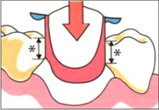
DENTURE BASE: it should be designed with broad coverage so that occlusal forces can be distributed over as wide an area as possible. The border extensions must not interfere with functioning of surrounding tissues.
IN CASE OF CLASS IV4,11:
If the numbers of missing teeth are many and length of edentulous span is long then, this case is to be treated as tooth-tissue supported as in distal extension cases otherwise proceed the case as tooth supported prosthesis. The clasp configuration to be used is quadrilateral one where the anterior clasps are placed as far anterior as possible and posterior clasps as far posterior as possible. Indirect retainer should be placed as far posterior to the fulcrum line as possible. Esthetic requirements of the patient are fulfilled very carefully. Also, efforts should be made to minimize the stresses.
IN CASE OF CLASS III: in these patients, cross-arch stabilization is required and quadrilateral clasp configuration is to be used.
PHASE 3: ADEQUATE SUPPORT FOR DISTAL EXTENTSION CASES1:concept of broad stress distribution has to be followed. The residual ridge area is recorded with functional impression while teeth are recorded with anatomic impressions because normally the teeth do not change the position under function to a measurable degree.
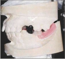
PHASE 4: ESTABLISHMENT OF HARMONIUS OCCLUSION1:
Centric occlusion and centric relation should coincide.
A harmonious occlusion should be established with no interceptive contacts and with all eccentric movements dictated by remaining natural teeth.
Artificial teeth selected should be narrower buccolingually.
For mechanical advantage, teeth should be positioned over the crest of the ridge.
PHASE 5: INITIAL PLACEMENT PROCEDURE:
Check for the fit of prosthesis. Any discrepancy that was present should be corrected.
PHASE 6: PEREIODIC RECALL1,11: it is very critical step for the recognition of changes in oral structures so that further steps can be taken to maintain oral health.. Usually 6 month recall period is adequate for most of the patients.
Conclusion:
Partially edentulous patients have many and varied needs. The clinician must understand the healthy physiological gnathostomatic system and properly diagnose what is pathological or physiological. The clinician goal should not only be to provide an esthetic and functional restoration but also a lasting harmonious state. Designing a RPD which optimally satisfies the requirement of support, function and esthetics had always been a challenge. Keeping in mind the "KISS" PRINCIPLES i.e. "Keep It Safe And Simple" in mind and utilizing the above given information, will help in meeting this challenge.
References:
1. Carr AB, McGivney GP, Brown DT. McCraken's Removable Partial Prosthodontics.11TH ED.
2. Davenport JC ,Basker RM, Heath JR, Ralph JP and Glantz PO. Need and demand for treatment. British Dental Journal 2000; 189: 364-368.
3. Davenport JC ,Basker RM, Heath JR, Ralph JP and Glantz PO. Surveying British Dental Journal 2000; 189: 532-541.
4. Davenport JC ,Basker RM, Heath JR, Ralph JP and Glantz PO. A system of design. British Dental Journal 2000; 189: 586-590.
5. Davenport JC ,Basker RM, Heath JR, Ralph JP and Glantz PO .Retention British Dental Journal 2000; 189: 646-657.
6. Davenport JC ,Basker RM, Heath JR, Ralph JP and Glantz PO and Hammond P. Bracing and reciprocation British Dental Journal 2001; 190: 10-14.
7. Davenport JC ,Basker RM, Heath JR, Ralph JP and Glantz PO and Hammond P .Clasp design British Dental Journal 2001; 190: 71-81.
8. Davenport JC ,Basker RM, Heath JR, Ralph JP and Glantz PO and Hammond P. Indirect retention British Dental Journal 2001; 190: 128-132.
9. Davenport JC, Basker RM, Heath JR, Ralph JP and Glantz PO and Hammond P. Connectors British Dental Journal 2001; 190: 184-191.
10. Davenport JC ,Basker RM, Heath JR, Ralph JP and Glantz PO and Hammond P. Tooth preparation British Dental Journal 2001; 190: 288-294.
11. Phoenix RD. Stewart's Clinical Removable Partial Prosthodontics.3RD ED. |