Introduction
There has been a rapid increase in the number of practitioners involved in implant placement, including specialists and general practioners with different levels of expertise. Although the significance of accurate planning and surgical guidance as it pertains to critical anatomic landmarks such as the mandibular canal, maxillary sinus, and adjacent teeth cannot be overstated when reviewing imaging modalities for the preoperative assessment of the dental implant site, many conflicting variables need to be considered. The amount of information provided, its accuracy, and its applicability need to be weighed against cost, convenience, availability, radiation dose, and expertise required to produce and read the output of each modality. Currently there are a number of software systems that analyze computerized tomography (CT) scans to aid in planning surgery and produce the physical surgical drilling template guides. These templates are computer manufactured in such a way that they identically match the location, trajectory, and depth of the planned implant. As the dental practitioner places the implants, the templates stabilize the drilling by restricting the degrees of freedom of the drill trajectory and depth. The quantitative relationship between successful outcomes in dental implant treatment and CT-based dental imaging, coupled with surgical template guidance, is unknown and awaits discovery through large prospective clinical trials. However, using CT-based dental imaging together with surgical template guidance is becoming a reliable procedure based on a series of recent preliminary clinical studies and case reports.1-4 The development of advanced imaging in recent years is breathtaking. Dentistry, as a whole, still needs some time to adapt to this rapid development in imaging. With the vastly improved diagnostic ability from CBCT, the treatment outcome becomes highly predictable. The quality of all dental patient care will be enhanced by it. One thing is sure: the change has just begun.
History
CBCT was first adapted for potential clinical use in 1982 at the Mayo Clinic Biodynamics Research Laboratory5. Initial interest focused primarily on applications in angiography in which soft-tissue resolution could be sacrificed in favor of high temporal and spatial-resolving capabilities. Since that time, several CBCT systems have been developed for use both in the interventional suite and for general applications in CT angiography.6,7 Exploration of CBCT technologies for use in radiation therapy guidance began in 1992, followed by integration of the first CBCT imaging system into the gantry of a linear accelerator in 1999. The first CBCT system became commercially available for oro-maxillofacial imaging in 2001 (NewTom QR DVT 9000; Quantitative Radiology, Verona, Italy. Commercially available CBCT systems for oro-maxillofacial imaging include the CB MercuRay and CB Throne (Hitachi Medical, Kashiwi-shi, Chiba-ken, Japan), 3D Accuitomo products (J. Morita Manufacturing, Kyoto, Japan), and iCAT (Xoran Technologies, Ann Arbor, Mich; and Imaging Sciences International, Hatfield, Pa). (Fig 1) Similar systems designed for point-of-service head and neck imaging have also recently become available (MiniCAT, Xoran Technologies; 3D Accuitomo and 3D Accuitomo 170, J Morita Manufacturing; ILUMA Cone Beam CT, IMTEC, Ardmore, Okla and GE Healthcare, Chalfont St. Giles, UK). The principle of CBCT is based on a fixed x-ray source and detector with a rotating gantry.(Fig 2)
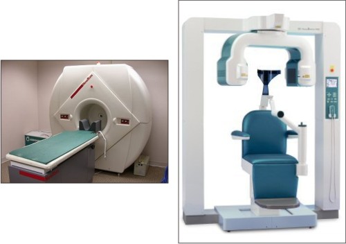 | Figure 1: Some currently available CBCT scan devices: New Tom 9000 Volumetric Imaging Device and J. Morita's 3D Accuitomo cone-beam CT
 |
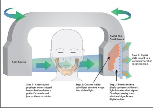 | Figure2. In cone beam computed tomography, a cone-shaped x-ray beam irradiates a patient's jaw. The transmitted x-rays are detected by a sensor. The data is then sent to a computer and reconstructed into 3-D images by software.
|
Oro-Maxillofacial Imaging
Advanced cross-sectional imaging techniques such as CT are used in Oro-maxillofacial imaging to solve complex diagnostic and treatment-planning problems, such as those encountered in craniofacial fractures, endosseous dental-implant planning, and orthodontics, among others. With the advent of CBCT technology, cross-sectional imaging that had previously been outsourced to medical CT scanners has begun to take place in dental offices.
Early dedicated CBCT scanners for dental use were characterized by Mozzo et al8 and Arai et al9 in the late 1990s. Since then, more commercial models have become available, inciting research in many fields of dentistry and oral and maxillofacial surgery. To date, multiple ex vivo studies have attempted to establish the ability of CBCT images to accurately reproduce the geometric dimensions of the maxillofacial structures and the mandible.10-13
A relatively low patient dose for dedicated maxillofacial scans is a potentially attractive feature of CBCT imaging. An effective dose in the broad range of 13-498 µSv can be expected, with most scans falling between 30 and 80 µSv, depending on exposure parameters. In comparison, CT with similar parameters delivers 860 µSv.14,15 Image quality can vary considerably with dose; images acquired with higher radiation exposure often produce superior image quality.
CBCT Benefits & Applications
Evaluation of the jaw bones to assess the position of the nerves in the lower jaw, and the sinuses and nose in the upper jaw.(Fig 3)
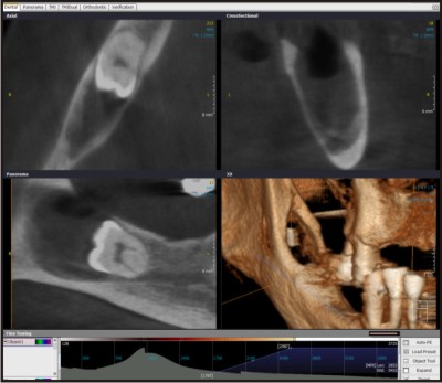
Evaluation of the bone for implant placement. (Fig 4)
Evaluation of abnormalities (pathology) in or affecting the bones (Fig 5)
Evaluation of the hard tissue (bones) of the tempro-mandibular joint (Fig 6)
Evaluate extent of alveolar ridge resorption
Assessment of relevant structures prior to orthodontic treatment such as the presence and position of impacted canine and third molar teeth
Assessing symmetry of the face (cephalometrics) (Fig 7)
Assessing the airway space (sleep apnea)
To permit 3D reconstructions of the bones or the fabrication of a Biomodel of the face and jaws
Assessing the mandibular nerve prior to the removal of impacted teeth, especially the lower wisdom teeth
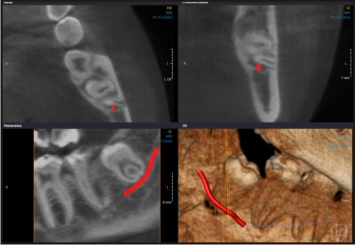 | Figure 3: Visualization of the intimate relation of the mandibular canal and an impacted wisdom tooth, imaged with the Scanora 3D.
|
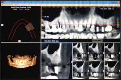 | Figure 4: Tomographic cone-beam computed tomographic images analyzed with iCAT software
|
 | Figure 5: Folicular dentigerous cyst in the right mandible associated with an impacted tooth, imaged with the Scanora 3D
|
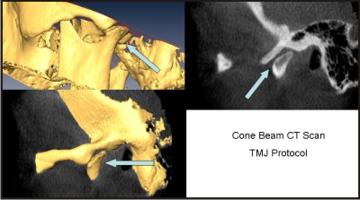 | Figure 6: Patient with flattening in the temporomandibular joint, imaged with the NewTom 3G.
|
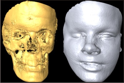 | Figure 7: A patient with deviation in the face in the right side, imaged with the NewTom
|
CBCT Versus Dental X-ray
Cone beam images provide undistorted or accurate dimensional views of the jaws. Panoramic images, by contrast, are both magnified and distorted. Magnification by itself is not a problem, as long as one knows or can calculate the magnification factor. Distortion, on the other hand, is the unequal magnification of different parts of the same image. Due to distortion panoramic images are notoriously unreliable to use for making measurements.16
In addition, while CT images can provide cross-sectional (bucco-lingual), axial, coronal, sagittal, and panoramic views, a panoramic film provides an image of only one dimension, namely a mesio-distal or antero-posterior perspective. Further, in a panoramic image all the structures between the x-ray tube and the image detector are superimposed on one another. With CT it is possible to separate out the various structures, for example, the left condyle from the right one.
CBCT Compared to Tomography
Unlike panoramic radiography, plain-film tomography, if performed with the appropriate equipment, does not result in distortion. Like panoramic radiography, however, it does result in magnification, the degree of which differs from manufacturer to manufacturer. Plain-film tomography provides direct (as opposed to reconstructed) cross-sectional, sagittal and coronal views. The disadvantage of plain-film tomography is that it requires much more chair time than CT. It can thus be especially difficult to do on patients who are unable to sit or hold still for a period of time. Cone beam CT, on the other hand, can be performed within a 10-40 second range, depending on the region being imaged and on the desired quality of the image. Cone beam CT also provides stronger indication of bone quality.
CBCT Versus CT
Cost of equipment is approximately 3-5 times less than traditional Medical CT
The equipment is substantially lighter and smaller.
Cone beam CTs have better spatial resolution (i.e. smaller pixels)
No special electrical requirements needed
No floor strengthening required
The room does not need to be cooled
Very easy to operate and to maintain; little technician training is required
Some cone beam manufacturers and vendors are dedicated to the dental market. This makes for a greater appreciation of the dentist 's needs
In the majority of cone beam CTs the patient is seated, as compared with lying down in a medical CT unit. This, together with the open design of the cone beam CTs virtually eliminates claustrophobia and greatly enhances patient comfort and acceptance. The upright position is also thought by many to provide a more realistic picture of condylar positions during a TMJ examination
The lower cost of the machine may be passed on to the patient in the form of lower fees
Both jaws can be imaged at the same time (depending on the specific cone beam machine)
Radiation dose is considerably less than with a medical CT.
Imaging Modalities In Dental Implant Placement
Implantologists have long appreciated the value of 3- dimensional imaging. Conventional CT scans are used to assess the osseous dimensions, bone density, and alveolar height, especially when multiple implants are planned. Locating landmarks and anatomy such as the inferior alveolar canal, maxillary sinus, and mental foramen occurs more accurately with a CT scan. The use of the third dimension has improved the clinical success of implants and their associated prostheses, and led to more accurate and aesthetic outcomes.16,17 With CBCT technology both the cost and effective radiation dose can be reduced. CBCT has been in use in implant therapy and may be employed in orthodontics for the clinical assessment of bone graft quality following alveolar surgery in patients with cleft lip and palate. The images produced provide more precise evaluation of the alveolus. This technology can help the clinician determine if the patient should be restored or if teeth should be moved orthodontically into the repaired alveolus. Anatomic structures such as the inferior alveolar nerve, maxillary sinus, mental foramen, and adjacent roots are easily visible using CBCT . The CBCT image also allows for precise measurement of distance, area, and volume. Using these features, clinicians can feel confident in the treatment planning for sinus lifts, ridge augmentations, extractions, and implant placements.
Before implant placement and during treatment planning, the implant clinician must be able to measure the height and width of the alveolar process to ensure adequate bone and to select appropriately sized implants. In addition, the clinician must know the precise location of the mandibular canal (injury to the neurovascular bundle within the canal can result in facial paresthesia) and the maxillary sinuses (perforation of the sinuses creates the possibility of antral infections and increases the likelihood of implant failure). Multiple views of the proposed implant site should be taken, which often require the use of different imaging procedures. Various radiographic modalities are available to the clinician, including intraoral films (i.e., periapical and occlusal radiographs), panoramic radiographs, cephalometric radiographs, plain (conventional) tomography, computed tomography (CT), cone beam CT, digital subtraction radiography, and magnetic resonance imaging.
Cross-sectional imaging techniques can be an invaluable tool during preoperative planning for complicated endosseous dental implantation procedures.19 Conventional linear tomography and CT have traditionally been used in presurgical imaging, though the former has overlain ghosting artifacts and the latter has relatively high radiation exposure and cost.20
Practitioners have begun using office-based CBCT scanners in preoperative imaging for implant procedures, capitalizing on availability and low dosing requirements.
Limitations of CBCT Imaging
While there has been enormous interest, current CBCT technology has limitations related to the "cone beam" projection geometry, detector sensitivity and contrast resolution. These parameters create an inherent image "noise" that reduces image clarity such that current systems are unable to record soft tissue contrast at the relatively low dosages applied for maxillofacial imaging. Another factor that impairs CBCT image quality is image artifact such as streaking, shading, rings and distortion. Streaking and shading artifacts due to high areas of attenuation (such as metallic restorations) and inherent spatial resolution may limit adequate visualization of structures in the dento-alveolar region.
Controversies
As with any emerging imaging technology, use of CBCT scanners has been the subject of criticism as well as acclaim21. The technology itself is limited by lack of user experience and what is currently a relatively small body of related literature. The point-of-service operational model that dominates diagnostic head and neck CBCT imaging practices has also drawn criticism. Because of the low radiation dose, CBCT can only provide bony detail and is unable to provide images of the soft tissues. Research on this technology is still preliminary, without prospective studies that convincingly demonstrate its benefit compared with conventional CT. Both in medical and oral and maxillofacial imaging in dentistry, CBCT has been largely adopted as an office-based service. This is a usage model purported to expedite patient diagnosis and treatment while simultaneously reducing costs, providing one-step management with fewer billed visits and no radiologist consultation fees. Point-of-service imaging and other self-referral services, however, have been widely criticized for encouraging overuse and directly inflating medical costs. The belief that financial incentives undermine the clinical decision-making process has been the basis for it's criticism. The advent of CBCT technologies has also fueled the controversy surrounding office-based imaging, which is usually performed and interpreted by non-radiologists often without the accreditation, training, or licensure afforded by the radiology community.
Conclusions
Outcomes assessment in this area of dentistry is difficult, primarily due to bias and variability in clinical research. Observed differences can be due to differences among investigators and/or interest groups rather than differences in the treatments. Furthermore, once cost-to-benefit analyses are conducted, the increase in cost associated with CT-based implant planning and computer fabrication of surgical templates must be justified from a consumer perspective (i.e., the value associated with the increased safety and predictability of dental implants). It helps the clinician to safely and predictably transfer the optimal-implant trajectory and distances from the adjacent tooth and mandibular nerve to the patient's mouth. The final restoration becomes functional and esthetic. It does not compromise adjacent teeth or anatomic structures, yet was well accepted by the patient. CBCT is an emerging CT technology, which has potential applications for imaging of high-contrast structures in the head and neck as well as maxillofacial regions. Preliminary research suggests that high-spatial-resolution images can be obtained with comparatively low patient dose. To date, the most researched applications for head and neck CBCT are in sinus, middle and inner ear implant, and maxillofacial imaging. This technology is not without controversy, and further research is required to establish informed recommendations about its appropriate use in a clinical setting.
References
1. Siessegger M, Schneider BT, Mischkowski RA, et al. Use of an image-guided navigation system in dental implant surgery in anatomically complex operation sites. J Craniomaxillofac Surg. 2001;29:276-281.
2. Fortin T, Champleboux G, Bianchi S, Buatois H, Coudert JL. Precision of transfer of preoperative planning for oral implants based on cone-beam CT-scan images through a robotic drilling machine. Clin Oral Implants Res. 2002;13: 651-656.
3. Tardieu PB, Vrielinck L, Escolano E. Computer-assisted implant placement, a case report: treatment of the mandible. Int J Oral Maxillofac Implants. 2003;18: 599-604.
4. Vrielinck L, Politis C, Schepers S, Pauwels M, Naert I. Image-based planning and clinical validation of zygoma and pterygoid implant placement in patients with severe bone atrophy using customized drill guides: preliminary results from a prospective clinical followup study. Int J Oral Maxillofac Surg. 2003; 32:7-14.
5. Robb RA. The dynamic spatial reconstructor: an x-ray video-fluoroscopic CT scanner for dynamic volume imaging of moving organs. IEEE Trans Med Imaging 1982;1:22-33
6. Fahrig R, Fox AJ, Lownie S, et al. Use of a C-arm system to generate true three-dimensional computed rotational angiograms: preliminary in vitro and in vivo results. AJNR Am J Neuroradiol 1997;18:1507-14
7. Saint-Fe´lix D, Trousset Y, Picard C, et al. In vivo evaluation of a new system for 3D computerized angiography. Phys Med Biol 1994;39:583-95
8. Mozzo P, Procacci C, Tacconi A, et al.Anew volumetric CT machine for dentalimaging based on the cone-beam technique: preliminary results. Eur Radiol 1998;8:1558-64
9. Arai Y, Tammisalo E, Iwai K, et al. Development of a compact computed tomographic apparatus for dental use. Dentomaxillofac Radiol 1999;28:245-48
10. Lascala CA, Panella J, Marques MM. Analysis of the accuracy of linear measurements obtained by cone beam computed tomography (CBCT-NewTom). Dentomaxillofac Radiol 2004;33:291-94
11. Mischkowski RA, Pulsfort R, Ritter L, et al. Geometric accuracy of a newlydeveloped cone-beam device for maxillofacial imaging. Oral Surg Oral Med Oral Pathol Oral Radiol Endod 2007;104:551-59. Epub 2007 Jul 5
12. Lagrave`re MO, Carey J, Toogood RW, et al. Three-dimensional accuracy ofmeasurements made with software on cone-beam computed tomography images. Am J Orthod Dentofacial Orthop 2008;134:112-16
13. Kumar V, Ludlow JB, Mol A, et al. Comparison of conventional and cone beam CT synthesized cephalograms. Dentomaxillofac Radiol 2007;36:263-69
14. Ludlow JB, Ivanovic M. Comparative dosimetry of dental CBCT devices and 64-slice CT for oral and maxillofacial radiology. Oral Surg Oral Med Oral Pathol Oral Radiol Endod 2008;106:106 -14. Epub 2008 May 27
15. Schulze D, Heiland M, Thurmann H, et al. Radiation exposure during midfacial imaging using 4- and 16-slice computed tomography, cone beam computed tomography systems and conventional radiography. Dentomaxillofac Radiol 2004;33:83-86
16. Serman NJ. Pitfalls of panoramic radiology in implant surgery. Ann Dent 1989;48:13-16.
17. Hatcher DC, Dial C, Mayorga C. Cone beam CT for pre-surgical assessment of implant sites. J Calif Dent Assoc.2003;31:825-833.
18. Almog DM, LaMar J, LaMar FR, et al. Cone beam computerized tomography- based dental imaging for implant planning and surgical guidance, Part 1: Single implant in the mandibular molar region. J Oral Implantol. 2006;32:77-81.
19. Tyndall DA, Brooks SL. Selection criteria for dental implant site imaging: a position paper of the American Academy of Oral and Maxillofacial Radiology. Oral Surg Oral Med Oral Pathol Oral Radiol Endod 2000;89:630-37
20. Lofthag-Hansen S, Gro¨ndahl K, Ekestubbe A. Cone-beam CT for preoperative implant planning in the posterior mandible: visibility of anatomic landmarks. Clin Implant Dent Relat Res 2008 Sep 9.
21. A.C. Miracle, S.K. Mukherji, Conebeam CT of the Head and Neck, Part 2:Clinical Applications, Aug 2009Am J Neuroradiol 30:1285-92 |