Introduction
The principal goal of dentistry is to maintain and improve the quality of life of the dental patients. This goal can be accomplished by preventing diseases, relieving pain, improving masticatory efficiency, enhancing speech and improving appearance. As many of these objectives require the replacement or alterations of the existing tooth structure, the main challenges for the centuries have been the development and selection of biocompatible materials that can withstand the unique conditions of the oral environment.
In recent years, dentistry has witnessed the introduction and subsequent withdrawal of numerous unsatisfactory products and techniques from the market. The failure of various products and techniques is mainly because of unique conditions of oral environment. These failures make the researchers to investigate relationship between laboratory research and clinical performance of the techniques and materials. So, all the laboratory or in-vitro studies should be done keeping the oral environment in mind [1].
Classical methods of mathematical stress analysis are extremely limited in their scope and are inappropriate for dental structures that have an irregular structural form and complex loading [2]. The finite element is a modern technique of numerical stress analysis that has the great advantage of being applicable to solids of irregular geometry and heterogeneous material properties. It is therefore ideally suited for the examination of structural behavior of the oral cavity.
The Finite element analysis (FEA) can be applied to many areas in engineering, biomedical engineering is among one of them. The development in main frame computers and availability of powerful microcomputers has brought this method within the reach of students and engineers. FEA is used in all fields of dentistry especially in implant dentistry [3]. The aim of this review article is to address the basics of FEA and its application in dentistry.
Material And Methods
Literature was selected through a search of PubMed, Embase and Cochrane electronic databases. The keywords used for search were finite element analysis; finite element analysis in dentistry; finite element analysis dental; finite element analysis dental implant. The search was restricted to English language articles related with the basics of finite analysis method and its application in dentistry.
History of FEA
The FEA originated from the need for solving complex elasticity and structural analysis problems in civil and aeronautical engineering. Its development can be traced back to the work by Alexander Hrennikoff [4] and Richard Courant [5]. The roots of the theory relates back to the Ritz method of numerical analysis, first introduced in 1909 [6]. Further development of these ideas continued through the 1940’s and 50’s. By 1953, engineers began to use computers to solve structural problems.
Development of the FEA began in earnest in the middle to late 1950’s for airframe and structural analysis. It gathered momentum at the University of Stuttgart through the work of John Argyris [7] and at Berkeley through the work of Ray W. Clough [8] in the 1960s for use in civil engineering. In 1963, FEA was recognized as a specific technique, and a serious academic discipline. With the advent of personal-computers in the 1980’s, the methods have become more widely used. It is now possible for engineers in virtually every industry to take advantage of this powerful tool.
Steps in the solution procedure using FEA
1. Discretization of problem
2. Imaging
3. Meshing
4. Boundary conditions
5. Types of solutions
Discretization of problem
Solving a real life problem with continuous material approach is difficult and the basic of all numerical methods is to simplify the problem by discretizing (discontinuation) it. In simple words, nodes work like atoms with gap in between filled by an entity called as element [9,10]. Calculations are made at nodes and results are interpolated for elements. There are two approaches to solve any problem:
1. Continuous approach (all real life components are continuous).
2. Discrete approach (equivalent mathematical modeling).
All the numerical methods including finite element follow discrete approach. Meshing (nodes and elements) is nothing but discretization of a continuous system with infinite degree of freedoms to finite degree of freedoms [9].
Imaging
a) Imaging and three-dimensional reconstruction. Recent innovations in computerized tomography (CT), magnetic resonance imaging (MRI), and confocal microscopy have revolutionized biological imaging. It is now possible to capture serial sections of virtually any structure and generate exquisitely detailed three-dimensional reconstructions. Three-dimensional surface reconstructions created from CT scans are used as templates for three-dimensional finite element models. Initial three-dimensional surface reconstructions are typically quite rough and require significant editing before they can be imported into a FE tool and successfully meshed as a finite element model [11].
b) Image processing: editing the three-dimensional image. Editing three-dimensional images is the most time intensive step in building FE models of biological structures. The ultimate goal of three-dimensional image processing is to generate a “water-tight” surface model that can be imported into and successfully manipulated in FE software.
The most important aspect of the simplification process of three-dimensional images involves smoothening and removing details in selected areas of the model. three-dimensional surface representations are composed of connected polygons and are often referred to as ‘polygon models’. The more polygons a model contains, the greater is its fidelity to the object it represents and the larger is its size. Image processing is the most labor-intensive aspect of conducting FE analyses of biological structures [11] (Figure 1 and Figure 2).
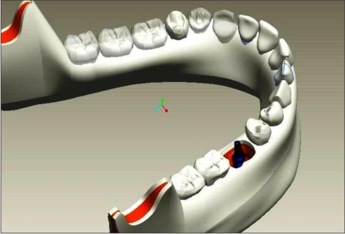 | Fig 1: CAD image of an implant placed in mandible.
 |
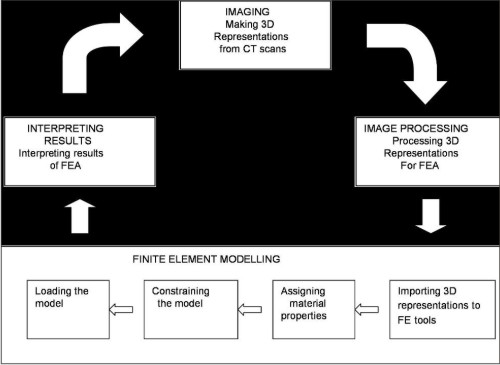 | Fig 2: Steps in FEA
|
Meshing
FEM uses a complex system of points (nodes) and elements, which make a grid called as mesh. Basic theme of FEA is to make calculations at only limited (finite) number of points and then interpolate the results for entire domain (surface or volume). Any continuous object has infinite degrees of freedom and it is just not possible to solve the problem in this format. FEA reduces degrees of freedom from infinite to finite with the help of discretization i.e. meshing (nodes and elements) as shown in Figure 3 [9].
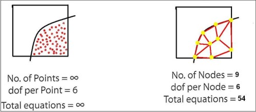 | Fig 3: Meshing
|
Two-dimensional meshing and three-dimensional meshing
Two-dimensional modeling is comparatively simple and it allows the analysis to be run on a relatively normal computer, but it also sometimes tends to yield less accurate results. For two-dimensional analysis, the element shapes are triangular, quadrilateral, and in three-dimensional analysis element shapes are tetra, penta, hex and pyramid. Three-dimensional modeling produces more accurate results, but it can run only on the fastest computers effectively [9].
Boundary Conditions
Boundary condition is application of force and constraint. Different ways to apply force and moment are concentrated load (at a point or single node), force on line or edge, distributed load (force varying as equation), bending moments and torque (Figure 4 shows boundary condition).
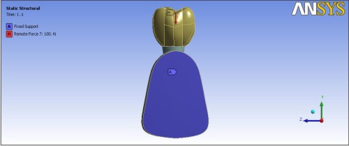 | Fig 4: Boundary conditions
|
After fixing the boundary conditions the software is run for determining stresses & strains using linear static analysis & non linear analysis [9].
Types of solutions
The above analysis is done to assess the stresses acting upon the materials during function in the oral cavity by applying various material properties (Table 1) [12-14]. These stresses are:
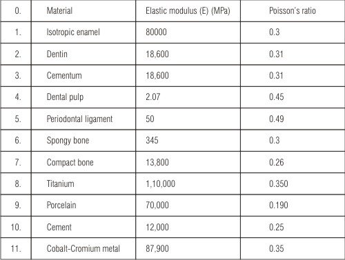 | Table 1. Mechanical properties used for different structures
|
1. Normal or principal stress: acts perpendicular to the cross section and causes elongation or compression.
2. Shear stress: acts parallel to the cross section and causes distortion (changes in original shape).
Whenever an elastic body is subjected to loads in its 3 dimensions, the stresses will get developed along the principal axis of the body. These are the principal stresses. There are three “principal stresses” that can be calculated at any point, acting in the x, y, and z directions. These stresses should not exceed the yield stress of the material.
There is a convention on listing the three principal stresses which makes the ‘first’ one the maximum of the three, and the ‘third’ one the minimum, which can be the maximum compressive (negative) stress, but may actually be a positive stress.
Maximum principal stress. The maximum principal stress gives the value of stress that is normal to the plane in which the shear stress is zero. The maximum principal stress helps you understand the maximum tensile stress induced in the part due to the loading conditions (Figure 5).
 | Fig 5: 2-D FEA Effect of tensile load around implant
|
Minimum principal stress. The minimum principal stress acts normaly to the plane in which shear stress is zero. It helps you to understand the maximum compressive stress induced in the part due to loading conditions (Figure 6).
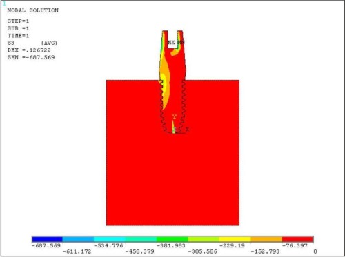 | Fig 6: 2-D FEA Effect of compressive load around implant
|
Von Mises stress. The von Mises criterion is a formula for calculating whether the stress combination at a given point will cause failure.
The von Mises criterion is a formula for combining three principal stresses into an equivalent stress, which is then compared to the yield stress of the material (Figure 7).
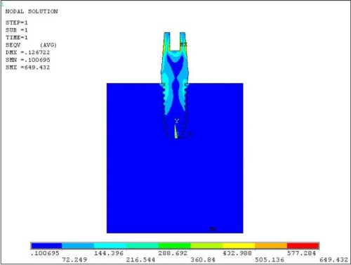 | Fig 7: 2-D FEA Vonmises stress around implant
|
The yield stress is a known property of the material and is usually considered for the failure stress. If the “von Mises stress” exceeds the yield stress, then the material is considered to be at the failure condition. The von Mises theory is used for ductile materials such as metals and evaluates stresses in both static and dynamic conditions [7,8].
Applications of finite element analysis
FEA makes it possible to evaluate a detailed and complex structure in a computer, during the planning of the structure. The demonstration in the computer of the adequate strength of the structure and the possibility of improving the design during planning can justify the cost of this analysis work. FEA has also been known to increase the rating of structures that were significantly overdesigned and built many decades ago.
In the absence of FEA (or other numerical analysis), development of structures must be based on hand calculations only. For complex structures, the simplifying assumptions required to make any calculations possible can lead to a conservative and heavy design. A considerable factor of ignorance can remain as to whether the structure will be adequate for all design loads. Significant changes in designs involve risk. Designs will require prototypes to be built and field tested. The field tests may involve expensive strain gauging to evaluate strength and deformation.
With FEA, the weight of a design can be minimized, and there can be a reduction in the number of prototypes built. Field testing will be used to establish loading on structures, which can be used to do future design improvements via FEA [15].
Applications of finite element analysis in dentistry
FEA has been applied for the description of form changes in biological structures (morphometrics), especially in the area of growth and development [16,17].
The knowledge of physiological values of alveolar stresses is important for the understanding of stress related bone remodeling and also provides a guideline reference for the design of dental implants [18-21].
FEA is also useful for designing and studying structures with inherent material homogeneity and potentially complicated shapes such as dental implants [22-25]. Analysis of stresses produced in the periodontal ligament under different loading conditions [26-29]. To study stress distribution in supporting structures of tooth in relation to different designs of fixed and removable prosthesis [30-33].To optimize the design of dental restorations [2,34,35]. To investigate stress distribution in tooth with cavity preparation and biomechanical preparation during root canal treatment [36,37].
The type of predictive computer model described may be used to study the biomechanics of tooth movement, whilst accurately assessing the effect of new appliance systems and materials without the need to go to animal or other less representative models.
Software used for finite element analysis
The various software used in FEA are Abaqus Explicit, Ansys, Dytran, Femfat, Hypermesh, Ls-dyna, Madymo, Magmasoft, MSC Nastran, Pro mechanica, Star-CD, Tosca, Unigraphics, etc [38,39].
Limitations of finite element analysis
Finite elements methods are extremely versatile and powerful and can enable designers to obtain information about the behavior of complicated structures with almost arbitrary loading. In spite of the significant advances that have been made in developing finite element packages, the results obtained must be carefully examined before they can be used [9].
The most significant limitation of FEA is that the accuracy of the obtained solution is usually a function of the mesh resolution. Any regions of highly concentrated stress, such as around loading points and supports, must be carefully analyzed with the use of a sufficiently refined mesh. In addition, there are some problems which are inherently singular (the stresses are theoretically infinite). Special efforts must be made to analyze such problems [9,10].
An additional concern for any user is that because current packages can solve so many sophisticated problems, there is a strong temptation to “solve” problems without doing the hard work of thinking through them and understanding the underlying mechanics and physical applications. Modern finite element packages are powerful tools that have become increasingly indispensable to mechanical design and analysis. However, they also make it easy for users to make big mistakes.
Obtaining solutions with FEA often requires substantial amounts of computer and user time. Nevertheless, finite element packages have become increasingly indispensable to mechanical design and analysis.
Summary & Conclusion
The finite element analysis is a relatively recent discipline that has quickly become a mature method, especially for structural analysis. The costs of applying this technology to everyday design tasks have been dropping, while the capabilities delivered by the method are expanding constantly. With education in the technique and in the commercial software packages becoming more and more available, the question has moved from “Why apply finite element analysis?” to “Why not?” The method is fully capable of delivering higher quality products in a shorter design cycle with a reduced chance of field failure, provided it is applied by a capable analyst. It is also a valid indication of thorough design practices, should an unexpected litigation crop up. The time is now for industry to make greater use of this and other analysis techniques.
It can be concluded that finite element analysis can be used in various fields of dentistry like Implant dentistry, Prosthodontics, Periodontics etc. to study the stress patterns related to structural behaviour of oral tissues.
References
1. Dejak B, Mlotkowski A, Romanowicz M. Finite element analysis of stresses in molars during clenching and mastication. J Prosthet Dent 2003; 90:591-7.
2. Verdonschot N, Fennis WM, Kuijs RH, Stolk J, Kreulen CM, Creugers NH. Generation of 3-D finite element models of restored human teeth using micro-CT techniques. Int J Prosthodont 2001; 14: 310-5.
3. Geng JP, Tan KB, Liu GR. Application of finite element analysis in implant dentistry: a review of the literature. J Prosthet Dent 2001; 85:585-98.
4. A. Hrenikoff. Solution of problems in elasticity by framework method. J Appli Mech 1941; A8: 169-75.
5. R. Courant. Variational methods for the solution of problems of equilibrium and vibration. Bull Am Math Soc 1943; 49: 1-23.
6. W. Ritz. Uber Eine neue methode zur losung gewissen variations- Probleme der mathematischem physic. J Reine Angew Math 1909;135: 1-61.
7. J. H. Argyris. Energy theorems and structural analysis. Butterworth, 1960 (reprinted from Aircraft Eng: 1954-5.
8. R. W Clough. The finite element in plane stress analysis. Proc 2nd ASCE Conf on electronic computation. Pittsburgh; Pa, Sept 1960.
9. Nitin Gokhale, Sanjay Deshpande, Sanjeev Bedekar, Anand Thite. Practical finite element analysis. 1st ed. Finite to infinite; 2008.
10. O. C. Zienkiewicz, R.L Taylor. Some preliminaries: the standard discrete system. In: The finite element method, Volume 1: The basics. 5th ed. Butterworth Heinemann; 2000.
11. FEA in biology (Homepage on the internet). Available from: http:// www.biomesh.org/basics.phtml.
12. Heng-Li Huang, Chin Han Chang, Jui Ting Hsu, Alison M Fallgatter, Ching Chang Ko Int J Oral Maxillofac Implants 2007 ; 22:551-562
13. O’Brien WJ. Dental materials and their selection. 2nd ed. Chicago: Quintessence; 2002. p. 347.
14. Yang HS, Lang LA, Molina A, Felton DA. The effects of dowel design and load direction on dowel-and-core restorations. J Prosthet Dent 2001;85:558-67.
15. Peter Budgell, Finite Element Analysis with ANSYS: Information and Tips, 1998 http://www3.sympatico.ca/peter_budgell/FEA_intro.html
16. Takeshita S, Sasaki A, Tanne K, Publico AS, Moss ML. The nature of human craniofacial growth studied with finite element analytical approach. Clin Orthod Res 2001; 4: 148-60.
17. Singh GD, Levy-Bercowski D, Yanez MA, Santiago PE. Three-dimensional facial morphology following surgical repair of unilateral cleft lip and palate in patients after nasoalveolar molding. Orthod Craniofac Res 2007; 10:161-6.
18. Borchers L, Reichart P. Three-dimensional stress distribution around a dental implant at different stages of interface development. J Dent Res 1983; 62(2): 155-9.
19. Siegele D, Soltesz U. Numerical investigations of the influence of implant shape on stress distribution in the jaw bone. Int J Oral Maxillofac Implants 1989; 4: 333-40.
20. Bergkvist G, Simonsson K, Rydberg K, Johansson F, Derand T. A Finite Element Analysis of stress distribution in bone tissue surrounding uncoupled or splinted dental implants. Clin Implant Dent Relat Res 2008;10 (1):40-6.
21. Ding X, Liao SH, Zhu XH, Zhang XH, Zhang L. Effect of diameter and length on stress distribution of the alveolar crest around immediate loading implants. Clin Implant Dent Relat Res 2008; Sep 9.
22. van Rossen IP, Braak LH, de Putter C, de Groot K. Stress - absorbing elements in dental implants. J Prosthet Dent 1990; 64 (2): 198-205.
23. Moroi HH, Okimoto K, Moroi R, Terada Y. Numeric approach to the bio-mechanical analysis of thermal effects in coated implants. Int J Prosthodont 1993; 6(6):564-72.
24. Canay S, Hersek N, Akpinar I, Asik Z. Comparison of stress distribution around vertical and angled implants with finite-element analysis. Quintessence Int 1996; 27(9):591-8.
25. Abu-Hammad O, Khraisat A, Dar-Odeh N, El-Maaytah M. Effect of dental implant cross-sectional design on cortical bone structure using Finite Element Analysis. Clin Implant Dent Relat Res 2007; 9(4):217-21.
26. Takahashi N, Kitagami T, Komori T. Behaviour of teeth under various loading conditions with finite element method. J Oral Rehabil 1980; 7(6): 453-61.
27. Atmaram GH, Mohammed H. Estimation of physiologic stresses with a natural tooth considering fibrous PDL structure. J Dent Res 1981;60(5):873-7.
28. Lee SY, Haung HM, Lin CY, Shih YH. In vitro and in vivo natural frequency analysis of periodontal conditions: an innovative method. J Periodontol 2000; 71:632-40.
29. Vandana KL, Karthik M. Finite element method: perio-endo concept. Endodontology 2004; 16: 38-41.
30. Yang HS, Thompson VP. A two-dimensional stress analysis comparing fixed prosthodontic approaches to the tilted molar abutment. Int J Prosthodont 1991; 4(5): 416-24.
31. Awadalla HA, Azarbal M, Ismail YH, el-Ibiari W. Three - dimensional finite element stress analysis of a cantilever fixed partial denture. J Prosthet Dent 1992; 68(2): 243-8.
32. Yang HS, Lang LA, Felton DA. Finite element stress analysis on the effect of splinting in fixed partial dentures. J Prosthet Dent 1999; 81: 721-28.
33. Molin MK, Onesti MP, Petersson TB, Derand TB. Three-dimensional finite element analyses of all ceramic posterior fixed partial dentures with different designs. Int J Prosthodont 2007; 20: 89-91
34. Toparli M, Aksoy T. Fracture toughness determination of composite resin and dentin / composite resin adhesive interfaces by laboratory testing and finite element models. Dent Mater 1998; 14: 287-93.
35. Toparli M, Gokay M, Aksoy T. Analysis of a restored maxillary second premolar tooth by using three-dimensional finite element method. J Oral Rehabil 1999; 26: 157-64.
36. Versluis A, Messer HH, Pintado MR. Changes in compaction stress distributions in roots resulting from canal preparation. Int Endod J 2006; 39: 931-9.
37. Rundquist BD, Versluis A. How does canal taper affect root stresses? Int Endod J 2006; 39:226-37.
38. Giuseppe Pelosi (2007). "The finite-element method, Part I: R. L. Courant: Historical Corner".
39. Babuska, Ivo; Uday Banerjee, John E. Osborn (June 2004). "Generalized Finite Element Methods: Main Ideas, Results, and Perspective". International Journal of Computational Methods 1 (1): 67–103. |