Introduction
The strength of silver soldered joints used to fabricate space maintainers and orthodontic appliances is critical to their success1,2. The appliance must be able to withstand the forces generated while masticating. Broken appliances compel patients for unscheduled office visits. Complications of broken appliances include soft tissue irritation, lost orthodontic anchorage, untoward movement of teeth and swallowing or aspiration of broken parts1. Research is meagred in terms of new materials and methods to help dental surgeons to fabricate stronger silver soldered joints. Various authors have evaluated different soldering techniques than the incorporation of different orthodontic wires to study the tensile strength of soldered joints.
For space holding appliances and in techniques where loops in arch wires are used cobalt-chromium wire is presently preferred over stainless steel. But heat treatment of Co-Cr wire results in a wire with properties similar to S.S3.
The mechanical properties of these wires are generally assessed by tensile bending and torsional tests. Although wire characteristics determined by these tests do not necessarily reflect the behaviour of these wires under clinical conditions, they provide a basis for comparison of these wires.
Hence, The Aim of The this Study was to Compare and Evaluate the Fracture Load of Silver Soldered Joints of Stainless Steel and Cobalt Chromium Orthodontic Wires with Band Material and In Various Orthodontic Joining configuration.
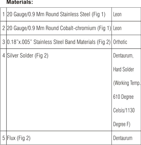
Materials And Methods :
Two types of wires and band materials used to test the tensile strengths of silver soldered joints in the study.
Armamentarium:
wire cutter, universal plier, band cutting scissors diamond disc, measuring scale, tweezer , plaster of paris , jig , aluminium blocks, rubber bowl.
Methods:
The specimens were assorted in the post graduate laboratory of the dept of orthodontics , j.s.s dental college and hospital,mysore
The tests were carried out at the dept of polymer science and technology, sri jayachamarajendra college of engineering ,mysore
Two types of wires and stainless steel band material were used to test the tensile strength of silver soldered joints in the study.
Orthodontic stainless steel wire(H.P) 0.9 mm , 0.9mm cobalt – chromium wire (leon) (Fig 1) and stainless steel band material (.018”x.005”) (ortho-organiser). (Fig 2)
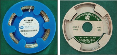 | Fig. 1: Wires
 |
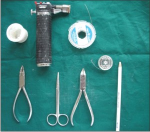 | Fig. 2: Armamentarium
|
The tensile strength of silver soldered joints was tested by preparing a total of sixty specimens out of them , thirty in stainless steel group and thirty in cobalt-chromium group. In each group sample were equally divided into three sub-group i.e., End to End (25mm in length), Round(25mm in length), and to orthodontic band (25mm in length) (Fig 3). Areas other than joint site were protected unnecessary exposure to heat from the soldering torch by plaster of paris blocks. Dentaurum silver solder and flux were used for soldering all joints. The joint site was adequately heated after application of the flux, with the reducing zone of the flame (Piezo gas burner2000,Japanese) and as soon as the site reached solder flow temperature, 6mm of solder was held in a tweezer and
introduced at the joint site. The flame was kept approximately 3/4th inch long throughout the soldering procedure. The flame was withdrawn when the
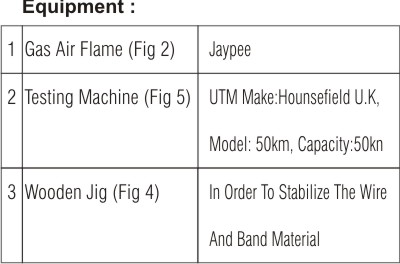
solder had flown over the joint site in a feather edge configuration. All specimens were immediately quenched in cold water as recommended by Phillips14. Tensile strength measurements were made of the joints using a Universal Testing Machine (Make: Hounsefield U.K., Model 50KM with a capacity of 50KN) (Fig 5) with a uniform crosshead speed of 2.00mm/min.
 | Fig. 3: Specimens
|
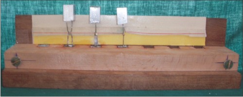 | Fig. 4: Wooden Jig
|
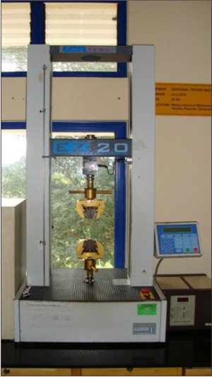 | Fig. 5: Universal Testing Machine (UTM)
|
The load at failure was recorded in Newtons. The broken samples were examined visually to determine where the failure had occurred, within the solder joint, wire or band fracture respectively. The tensile strength values in N/mm of the joint length were then determined / calculated for comparative evaluation of the tensile strength of silver soldered joints.
Results-
Statistical analysis – independent samples test was performed.
1. The mean tensile strength values of soldered joints for the various groups i,e., cobalt-chromium(Co-Cr) and stainless steel(S.S) in the study ,
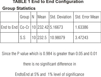
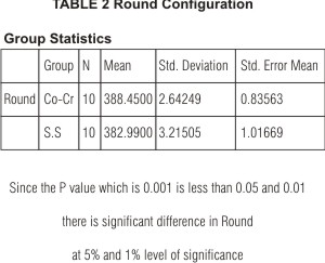
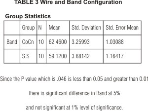
Co-Cr (End to End, Round & Wire to band) - 232.42 N/mm, 388.45N/mm & 62.46N/mm respectively and S.S (End to End, Round & Wire to band) - 232.5N/mm, 382.99N/mm & 59.12N/mm respectively.
Hence mean tensile strength cobalt-chromium was superior compared with that of stainless steel (Round and band to wire configuration).
2. Comparison of tensile strength of soldered joints on various configuration of Co-Cr and S.S wires groups
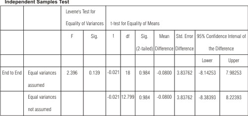
a. End to End -Independent samples test (Table 1) was conducted for different wire groups and it revealed that between different wires a no significant difference existed in their mean tensile strength values of soldered joints at 0.05 & 0.01 level (F= value 2.396, p=0.984 >0.05 and 0.01)
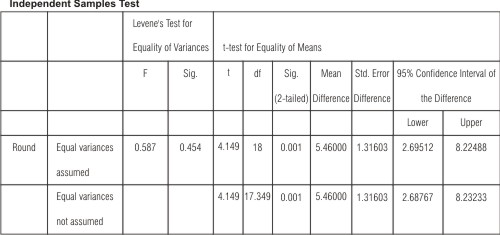
b. Round- Further , on same test (Table 2) was conducted it revealed that between different wires, a significant difference existed in their mean tensile strength values of soldered joints @ 0.05 & 0.01 level( F=0.587, P=0.001 < than 0.05& 0.01)
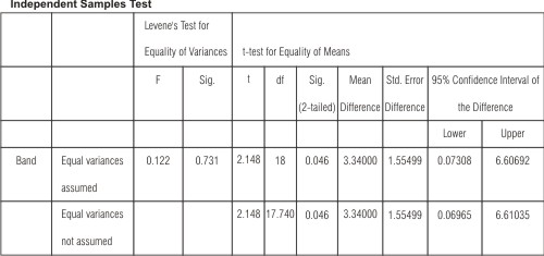
c. Band to wire, (Table 3) no significant difference existed in their mean values of soldered joints @ 0.05 & 0.01 level (F=0.122, P=0.046 > than 0.05 &0.01)
3. Fracture Site Determination
Determination of fracture site (Graph 1,2) for various wire groups have been discussed separately later , since no statistical tests have been applied on the obsereved values.
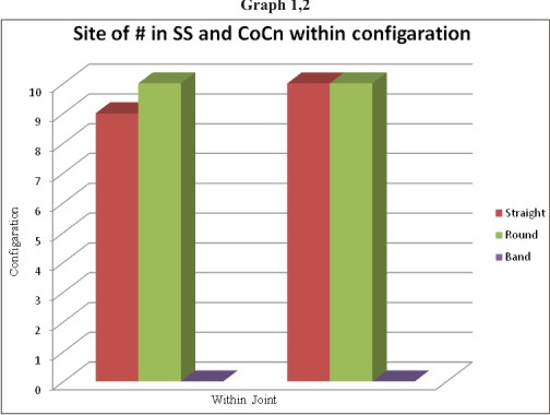 | Graph 1- Site Of Fracture In Stainless Steel And Cobalt-chromium Within Configuration (With In Joints- End To End And Round Configuration)
|
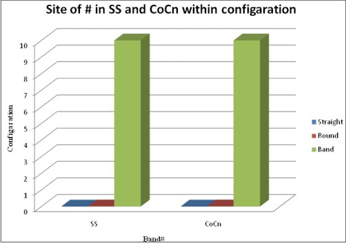 | Graph 2- Site Of Fracture In Stainless Steel And Cobalt Chromium Within Configuration (Wire And Band Configuration)
|
Discussion:
Silver soldering of wires for the fabrication of appliances typically involves overlap of wires with bands, crowns and other wires. It is important that the solder wraps around the wires so that the relatively weak solder has sufficient mass to strengthen the joint. The edges of the solder ought to be feathered onto the wire so that no crack is left for agents to enter and start a corrosive action. Evidence indicates that no alloying occurs at the stainless steel-silver solder interface and that the bond is strictly mechanical.
The tensile strength of a silver soldered joint is affected by the design, of the joint, the metallurgy of the joint and the stress distribution within the joint. Ideally, the joint strength should be as great as that of the parent metals being joined although if intermetallic layers are formed at the metal / solder interface, weakening effects may result. In general though, the interatomic force between the solder and parent metal (wire / band material) is considerably greater than that of either the parent metal or the solder. Consequently fracture occurs within the weaker material
In fabrication of appliances when loops in arch wires are used Co-Cr wire is presently preferred over S.S Co-Cr wires possesses the ability to be soldered as S.S wires. It has also been found to be easier to manipulate than S.S wires. Hence Co-Cr was also incorporate as one of the wire groups in the study.
For proper comprehension and convenience the discussion has been dealt under the headings
1. The mean tensile strength values of soldered joints for the various groups i,e., cobalt-chromium(Co-Cr) and stainless steel(S.S) in the study . (Table 1,2,3)
Co-Cr (End to End, Round & Wire to band) - 232.42 N/mm, 388.45N/mm & 62.46N/mm respectively and S.S (End to End, Round & Wire to band) - 232.5N/mm, 382.99N/mm & 59.12N/mm respectively.
2. determination of site of fracture- (Graph 1,2)
All specemins were visually examined to determine whre the failure had occurred outside the solder joint (wire , band material or within it)
a. For Co-Cr wire soldered end to end joint configuration all 10 samples tested for tensile strength fracture within joint and in S.S wires End to End joints out of 10 samples maximum fractured within joint one sample experienced a wire fracture
b. Both Co-Cr & S.S were soldered as Round joints configuration all samples fractured within the joint.
c. Both Co-Cr & S.S were soldered to band material all fractured at the band site
Unavoidable overheating of S.S band material which destroys its temper and resiliency along with its lower tensile strength may have led to more band fractures. however in order to arrive proper conclusion , further research using band material and wire of comparable tensile need to be conducted.
Conclusion:
From the study it can be concluded that all the three material viz. S.S , Co-Cr , band material may be used for preparing silver soldered joints irrespective of the properties and quality of wire.-However when subjecting the wire to joint site preparation, Gloria (S.S.) wire should be used keeping its limitations in view.
REFERENCES
1. Gawlik J.A., Mathieu G.P., and Hondurum S.: "The effects of tack welding and increasing surface area on the tensile strength of silver, electric and flame soldered stainless steet joints". J. Am. Acad. Ped. Dent., 1996; 18 (3).
2. O' Toole T.J., Furnish G.M. and Von Fraunhofer J.A.: "Tensile strength of soldered joints". J Prosthet Dent, 1985; 53 (3):50 - 352
3. Brown T., Mitchell R. and Barnie J. : "Evaluation of five silver soldering techniques". J Pedod 1982; 6: 235 - 43.
4. Cattaneo G., Wagnild G., Marshall G. and Watanabe L. "Comparison of tensile strength of solder joints by infrared and conventional torch technique". J Prosthet. Dent 1992; 68(1): 33-37.
5. Chaves M., Vermilyea S.G., Papazoglou E. and Brantely W.E. "Effects of three soldering techniques on the strength of high-palladium alloy solder joints". J Prosthet. Dent 1998; 79 (6): 677 - 84. 5
6. Cheng A.C., Chai J.Y., Gilbert J. and Jameson L.M. "Investigation of stiffness and microstructure of joints soldered with gas-oxygen torch and infrared methods". J. Prosthet. Dent 1994; 72 (1): 8 - 15.
7. Cheng A.C., Chai J.Y., Gilbert J. and Jameson L.M. "Mechanical properties of metal connectors soldered by gas torch versus an infrared technique". J Prosthodontic 1993; 2(2): 103-109.
8. Gardiner J.H. and Aamdot A.C. : "Some aspects of soldering stainless steel: A metallurgical investigation". Dent Practit 1969; 20: 65 - 76.
9. Gulkar I.A., Martini R.T., Zinner I.D. and Panno F.V. : "A comparison of hydrogen / oxygen and natural gas / oxygen torch soldering techniques". Int J Prosthodont 1994; 7: 258 -263.
10. Laird W.R.E. and Von Fraunhefer J.A.: "Silver soldered joints in stainless steel a comparative evaluation of techniques". Br Dent J 1972; 132: 263 - 267.
11. Limaverde Marcus A.R. and Stein R.S. : "Evaluation of soldered connectors of two base metal ceramic alloys". J Prosthet Dent 1994; 71: 339 - 344.
12. Tehini G.E. and Stein R.S. 1993. "Comparative analysis of two techniques for soldered connectors." J Prosthet Dent 1994; 69: 16- 19.
13. Wiskott H.W. A., Macheret R, Bussy R, Belser U.C. and Med Dent. : "Mechanical and elemental characterization of solderxjoints and welds using a gold-palladium alloy". J. ProsthetxDent 1997; 77: 607-616.
14. Phillips R.W. "Wrought base metal alloys wrought gold alloys.xIn skinners science of dental materials". 9th Ed.,xPhiladelphia: WB Saunders Co. 1991; 537 - 57. 14.
15. Rogers O.W. : "A metallographic evaluation of the stainlessxsteel silver solder joint". Aus Dent J 1979; 24 (1): 13 - 16.
16. Adams J. W.: "Stainless Steel in Dentistry and Orthodontics".Dent Clin North Am 1958; 2: 783 - 88. |